
Op-Amp Feedback Configurations
Interactive Audio Lesson
Listen to a student-teacher conversation explaining the topic in a relatable way.
Introduction to Op-Amp Feedback
🔒 Unlock Audio Lesson
Sign up and enroll to listen to this audio lesson

Welcome class! Today we’ll dive into Op-Amp feedback configurations. Can anyone tell me what feedback means in the context of operational amplifiers?

Isn’t it about feeding part of the output back to the input to control the gain?
Great point! Feedback is essential for controlling circuit behavior. We have both positive and negative feedback. What do you think is the common type used in linear applications?

I think it's negative feedback because it helps stabilize the output.
Exactly! Negative feedback helps improve linearity and stability by reducing overall gain. Let's remember this with the acronym 'SILVER' - Stability, Inversion, Linearity, Voltage range, Efficiency, and Reduced noise. Now, could anyone give me an example of when we might use positive feedback?

Maybe in comparators or oscillators?
Absolutely. Comparators can cause quick changes in output based on input signal levels. Now, let’s summarize: negative feedback enhances stability and control, while positive feedback supports amplification in specific applications.
Inverting Amplifier Configuration
🔒 Unlock Audio Lesson
Sign up and enroll to listen to this audio lesson

Let’s move on to the inverting amplifier configuration, which uses negative feedback to invert the input signal. Can anyone describe how this circuit is typically set up?
The input signal goes to the inverting terminal through a resistor, and there's a feedback resistor from the output to the inverting terminal.
Exactly! The non-inverting terminal is often grounded. Let's remember this with the mnemonic 'I GROW' - Input to Ground, Resistor at Output with feedback. Who knows the gain equation for this configuration?

It’s Av = -Rf/Rin, right?
Right! Now, if R₁ is 10 kΩ and R₂ is 100 kΩ, what does that make our gain?
That would be -10.
Fantastic! A final note, inverting amplifiers are valued for their precision and stable gain. Let's move to the next configuration.
Non-Inverting Amplifier Configuration
🔒 Unlock Audio Lesson
Sign up and enroll to listen to this audio lesson
In our next segment, we examine the non-inverting amplifier configuration. Who can explain how it differs from the inverting amplifier?
The input is connected directly to the non-inverting terminal, so the output isn't inverted.
Correct! In addition, the gain formula here is Av = 1 + Rf/Rin. Can anyone share why this configuration might be preferred?
It has high input impedance, so it won't load down the previous stage.
Exactly! It’s perfect for applications like voltage followers. Let’s summarize: a non-inverting configuration amplifies without inversion and retains phase integrity. Moving forward, what else is important about its gain?
The gain is always greater than or equal to 1.
Very well! These key advantages make it widely used in various electronic applications.
Differential Amplifier Configuration
🔒 Unlock Audio Lesson
Sign up and enroll to listen to this audio lesson
Now let's delve into the differential amplifier, which amplifies the difference between two input signals. Why do you think this is important?
It allows us to reject common-mode noise and focus on the desired signal!
Exactly! This is vital for applications in instrumentation and data acquisition. So, how is this configuration set up?
We apply one input to each input terminal of the Op-Amp, and we use several resistors to set the gain.
Correct! The gain is set using the resistors R₁, R₂ for the non-inverting input and R₃, R₄ for the inverting input. Repeat after me: R1 and R2 set the gain for the non-inverting input, R3 and R4 for the inverting input. Can anyone simplify the gain formula for a differential amplifier?
It’s Av = R2/R1 = R4/R3!
Well done! This relationship enables precise signal processing and conditioning. Let’s wrap this up by highlighting its role in reducing noise.
Design Exercises and Summary
🔒 Unlock Audio Lesson
Sign up and enroll to listen to this audio lesson
Finally, let’s put our knowledge into practice with some design exercises! How would you design an inverting amplifier for a gain of -20?
We’d set R₁ to 1 kΩ and calculate R₂ to be 20 kΩ.
Excellent! What about a non-inverting amplifier with a gain of 11?
We could use R₁ as 10 kΩ, making R₂ 100 kΩ.
Perfect! Finally, for a differential amplifier with a gain of 10, what resistors would you select?
I’d choose R₁ and R₃ at 10 kΩ, giving R₂ and R₄ at 100 kΩ.
Great teamwork, everyone! In summary, we have learned about the importance of feedback in Op-Amps, explored configurations like inverting, non-inverting, and differential amplifiers, and practiced practical design applications. Let's keep exploring these concepts!
Introduction & Overview
Read summaries of the section's main ideas at different levels of detail.
Quick Overview
Standard
In this section, we explore the purpose of feedback in Op-Amps, differentiating between negative and positive feedback. We cover key configurations like inverting, non-inverting, and differential amplifiers, emphasizing their circuit designs, gain equations, and practical applications in electronics.
Detailed
Op-Amp Feedback Configurations
Feedback in operational amplifiers (Op-Amps) is crucial for controlling circuit behavior, affecting key parameters like gain, stability, and frequency response. Two primary feedback types are considered:
- Negative Feedback: This is the most common type used in linear applications, where the output is fed back to the inverting input, reducing the overall gain but enhancing linearity and stability.
- Positive Feedback: Feedback is directed to the non-inverting input, which can amplify the output but may lead to instability or oscillation. This type is typically utilized in specific applications like comparators and oscillators.
This chapter focuses primarily on negative feedback configurations:
- Inverting Amplifier: This circuit configuration inverts and amplifies the input signal. The voltage gain is determined by the ratio of feedback and input resistors (Av = -Rf/Rin). Example: for R₁ = 10 kΩ and R₂ = 100 kΩ, the output is amplified by -10.
- Non-Inverting Amplifier: Here, the input signal is applied directly to the non-inverting terminal, offering amplification without inversion (Av = 1 + Rf/Rin). For R₁ = 10 kΩ and R₂ = 100 kΩ, the output is 11 times the input while keeping it in-phase.
- Differential Amplifier: This configuration amplifies the difference between two input signals and is vital in applications where differential signals are present, such as in audio systems. The gain is determined by several resistors.
The section concludes with design exercises showcasing practical applications of these configurations.
Youtube Videos
Audio Book
Dive deep into the subject with an immersive audiobook experience.
Introduction to Op-Amp Feedback
Chapter 1 of 4
🔒 Unlock Audio Chapter
Sign up and enroll to access the full audio experience
Chapter Content
Feedback in operational amplifiers (Op-Amps) is used to control the behavior of the circuit and achieve desired output characteristics, such as gain, stability, and frequency response. Feedback can be positive or negative, with negative feedback being the most common in linear applications.
● Negative Feedback: The output is fed back to the inverting input to reduce the overall gain and improve linearity, stability, and bandwidth.
● Positive Feedback: The output is fed back to the non-inverting input, resulting in a higher gain and often leading to instability or oscillation (typically used in comparators or oscillators).
In this chapter, we will focus on negative feedback configurations, which are widely used in Op-Amp circuits for amplification, filtering, and signal conditioning.
Detailed Explanation
In operational amplifiers, feedback refers to the process of taking a portion of the output signal and feeding it back into the input. This process is essential because it helps control how the amplifier behaves, helping achieve specific characteristics like gain, stability, and frequency response. Feedback can be divided into two types:
- Negative Feedback: This is the most common type, where the output is connected back to the inverting input. It helps stabilize the amplifier by reducing gain and improving performance.
- Positive Feedback: This type connects the output back to the non-inverting input, increasing the circuit's gain but potentially causing instability.
This chapter primarily focuses on negative feedback configurations, which are essential in applications like signal amplification and filtering.
Examples & Analogies
Think of an operation like driving a car. If you want to maintain a steady speed, you might occasionally check your speedometer and adjust the accelerator pedal accordingly. This is akin to negative feedback, where you modify your input (the accelerator) based on the feedback (the speedometer reading) to achieve the desired output (maintaining speed). Positive feedback, on the other hand, is like pressing the accelerator down harder without checking the speed, leading to potential loss of control.
Inverting Amplifier Configuration
Chapter 2 of 4
🔒 Unlock Audio Chapter
Sign up and enroll to access the full audio experience
Chapter Content
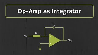
An inverting amplifier configuration uses negative feedback to invert and amplify the input signal. The basic circuit consists of an Op-Amp with a resistor at the input (R₁) and a feedback resistor (R₂) between the output and the inverting input.
● Circuit Description:
○ The input signal is applied to the inverting terminal of the Op-Amp through resistor R₁.
○ The non-inverting terminal is typically grounded.
○ The feedback resistor R₂ connects the output to the inverting input.
● Ideal Gain Equation:
The voltage gain of the inverting amplifier is given by the equation:
Av=−RfRin
Where:
○ R_f is the feedback resistor (R₂).
○ R_{in} is the input resistor (R₁).
● Design Considerations:
○ The gain is determined by the ratio of the feedback resistor and the input resistor.
○ The output voltage is inverted relative to the input signal.
● Advantages:
○ High precision and stable gain.
○ Simple design for amplification purposes.
● Example:
Suppose R₁ = 10 kΩ and R₂ = 100 kΩ. The voltage gain will be:
Av=−100k10k=−10
Thus, the output will be 10 times the input but inverted.
Detailed Explanation
An inverting amplifier uses a specific configuration of an op-amp circuitry to invert and amplify an input signal. Here's how it works:
1. Circuit Setup: The input signal connects to the inverting terminal of the op-amp through a resistor known as R₁. The non-inverting terminal is usually grounded. The feedback resistor R₂ connects the output of the op-amp to its inverting input.
2. Voltage Gain: The gain of the inverting amplifier is calculated using the formula Av = -R_f/R_in, where R_f is the resistor enabling feedback (R₂) and R_in is the input resistor (R₁). A negative sign indicates that the output will be inverted (180 degrees out of phase) relative to the input.
3. Practical Example: If R₁ is 10 kΩ and R₂ is 100 kΩ, substituting these values into the gain formula yields a gain of -10, meaning if you provide an input voltage, the output voltage will be 10 times larger but inverted.
Examples & Analogies
Imagine that you are using a seesaw. If you sit at one end (the input signal) and a friend sits at the other end with more weight (the feedback resistor), the seesaw will tip to your friend's side (inverted output). The further your friend moves from the center (like increasing R₂), the more pronounced the tipping effect (amplification) becomes, though the seesaw remains inverted relative to your position.
Non-Inverting Amplifier Configuration
Chapter 3 of 4
🔒 Unlock Audio Chapter
Sign up and enroll to access the full audio experience
Chapter Content
A non-inverting amplifier configuration uses negative feedback to amplify the input signal without inversion. The basic circuit consists of an Op-Amp with the input signal applied directly to the non-inverting terminal and a feedback resistor between the output and the inverting terminal.
● Circuit Description:
○ The input signal is applied to the non-inverting terminal of the Op-Amp.
○ The inverting terminal is connected to the output through resistor R₂.
○ The non-inverting terminal is connected to the input signal directly.
● Ideal Gain Equation:
The voltage gain of the non-inverting amplifier is given by the equation:
Av=1+RfRin
Where:
○ R_f is the feedback resistor (R₂).
○ R_{in} is the resistor between the inverting terminal and ground (R₁).
● Design Considerations:
○ The gain is always greater than or equal to 1.
○ The output voltage is in-phase with the input signal.
● Advantages:
○ Provides a high input impedance.
○ Ideal for use in voltage follower and buffering applications.
● Example:
Suppose R₁ = 10 kΩ and R₂ = 100 kΩ. The voltage gain will be:
Av=1+100k10k=11
Thus, the output will be 11 times the input and in-phase.
Detailed Explanation
The non-inverting amplifier configuration is designed to amplify an input signal without inverting it. Here are its key elements:
1. Circuit Setup: In this configuration, the input signal goes directly to the non-inverting terminal of the op-amp. The inverting terminal is connected back to the output through a resistor R₂, while the input resistor R₁ is connected to the ground.
2. Voltage Gain: The gain for this configuration is calculated through the formula Av = 1 + R_f/R_in, where R_f is the feedback resistor (R₂) and R_in is a resistor between the inverting terminal and the ground (R₁). The gain is always greater than or equal to 1, meaning the output will never be less than the input signal.
3. Example: If R₁ is 10 kΩ and R₂ is 100 kΩ, substituting these values into the gain formula gives a result of 11. This means the output voltage will be 11 times higher than the input voltage and in phase with it.
Examples & Analogies
Think of a non-inverting amplifier like a microphone amplifying your voice. When you speak into the microphone (input signal), it picks up your voice and amplifies it through a speaker (output) without changing how you sound (no inversion). The more gain you apply, the louder your voice sounds through the speaker, just like R₂ increases the output voltage relative to the input.
Differential Amplifier Configuration
Chapter 4 of 4
🔒 Unlock Audio Chapter
Sign up and enroll to access the full audio experience
Chapter Content
The differential amplifier is an Op-Amp configuration that amplifies the difference between two input signals. This configuration is widely used in instrumentation, audio systems, and data acquisition systems where the difference between two signals is important.
● Circuit Description:
○ The two input signals are applied to the inverting and non-inverting terminals of the Op-Amp.
○ Resistors R₁, R₂, and R₃ are used to set the gain for both inputs.
● Ideal Gain Equation:
The voltage gain of the differential amplifier is given by:
Av=RfRin=R2R1=R4R3
Where:
○ R₁ and R₂ set the gain for the non-inverting input.
○ R₃ and R₄ set the gain for the inverting input.
● Design Considerations:
○ The output voltage is proportional to the difference between the two input voltages.
○ It is used for signal conditioning and amplification of differential signals.
● Advantages:
○ Reduces common-mode noise.
○ Useful in applications where differential signals need to be amplified.
● Example:
For a differential amplifier with R₁ = 10 kΩ, R₂ = 100 kΩ, R₃ = 10 kΩ, and R₄ = 100 kΩ, the voltage gain will be:
Av=R2R1=100k10k=10
Thus, the output will be 10 times the difference between the two input signals.
Detailed Explanation
The differential amplifier is a specific configuration of the op-amp that amplifies the difference between two input signals. Here's how it works in a step-by-step manner:
1. Circuit Design: The differential amplifier uses an op-amp with two input terminals. Signal A goes to the non-inverting terminal, while Signal B goes to the inverting terminal. Resistors R₁, R₂, R₃, and R₄ are configured to control the gain for both inputs.
2. Voltage Gain: The gain of the differential amplifier can be expressed as Av = R2/R1 = R4/R3. This indicates the output is proportional to the difference between the two input signals, providing an important function in many applications, such as instrumentation.
3. Example: With R₁ = 10 kΩ, R₂ = 100 kΩ, R₃ = 10 kΩ, and R₄ = 100 kΩ, you can substitute these values into the gain formula. The gain comes out to be 10, meaning the output is ten times the difference between the two input signals.
Examples & Analogies
Consider a balance scale. When you put different weights on both sides (input signals), the scale will show you the difference, which is crucial for determining if one side is heavier than the other. This is similar to how a differential amplifier reveals the difference between two signals, making it useful in systems that need precise measurements, like laboratories or audio equipment.
Key Concepts
-
Feedback: The process of routing part of the output back to the input to regulate circuit performance.
-
Inverting Amplifier: Inverts the input signal and provides a voltage gain defined by Rf/Rin.
-
Non-Inverting Amplifier: Retains the phase of the input and provides a voltage gain of 1 + Rf/Rin.
-
Differential Amplifier: Amplifies the voltage difference between two inputs and rejects common-mode noise.
Examples & Applications
Inverting Amplifier: Given R₁ = 10 kΩ and R₂ = 100 kΩ, the gain is calculated as Av = -100k/10k = -10.
Non-Inverting Amplifier: Where R₁ = 10 kΩ and R₂ = 100 kΩ, the gain is calculated as Av = 1 + 100k/10k = 11.
Differential Amplifier: For R₁ = 10 kΩ, R₂ = 100 kΩ, R₃ = 10 kΩ, and R₄ = 100 kΩ, the gain is calculated as Av = 100k/10k = 10.
Memory Aids
Interactive tools to help you remember key concepts
Rhymes
For inverting gain, a twist we stake, negative values the output will make.
Stories
Imagine a two-way street where signals travel in opposite directions; the differential amplifier filters out noise and amplifies the important dialogue between two cars.
Memory Tools
Remember 'IN' for Inverting and 'NON' for Non-Inverting to recall which way they affect the input signal phase.
Acronyms
Remember 'GREAT' for gain configuration
Gain Reduction Enhances Amplifier Tuning.
Flash Cards
Glossary
- Operational Amplifier (OpAmp)
An integrated circuit that can amplify voltage signals.
- Feedback
Routing a portion of the output back to the input to control the performance of the circuit.
- Negative Feedback
Feedback that reduces the overall gain and enhances stability and linearity.
- Positive Feedback
Feedback that increases the gain, potentially leading to instability.
- Inverting Amplifier
An Op-Amp configuration that amplifies and inverts the input signal.
- NonInverting Amplifier
An Op-Amp configuration that amplifies the input signal without inversion.
- Differential Amplifier
An Op-Amp configuration that amplifies the difference between two input signals.
Reference links
Supplementary resources to enhance your learning experience.