
Transfer Function of an Ideal ADC
Enroll to start learning
You’ve not yet enrolled in this course. Please enroll for free to listen to audio lessons, classroom podcasts and take practice test.
Interactive Audio Lesson
Listen to a student-teacher conversation explaining the topic in a relatable way.
Understanding ADC Resolution and Stair-Step Characteristics
🔒 Unlock Audio Lesson
Sign up and enroll to listen to this audio lesson

Today, we’ll understand the transfer function of an ideal ADC. Can anyone tell me what we mean by 'resolution' in this context?

Is it about how accurately the ADC can convert an analog signal to a digital one?
Exactly! Resolution is defined as the smallest change in input voltage that can be detected, which we express as the Least Significant Bit, or LSB. The formula we use is: LSB = (Vmax - Vmin) / (2^N). Does anyone remember how N influences this?

A higher N means more bits, which leads to finer resolution.
Right! Higher bits increase precision. Now, let’s discuss how the output code is determined by the input voltage. The code is calculated as: Code = ⌊(Vin - Vmin) / LSB⌋. Can anyone explain why we use the floor function here?

The floor function makes sure we only get whole numbers for our digital output, right?
Exactly, good job! This discretization leads to a stair-step characteristic. Let’s summarize: ADC resolution and the stair-step output code are crucial for understanding how signals are processed in digital form.
Importance and Applications of ADC Transfer Functions
🔒 Unlock Audio Lesson
Sign up and enroll to listen to this audio lesson

Let’s dive deeper into why knowing the transfer function of an ADC is important in real applications. For starters, what might happen if our resolution is too low?

We might miss small changes in the data we're measuring, leading to inaccurate results.
Exactly! Applications like audio processing or precision instrumentation need high-resolution ADCs to capture details. Can someone explain how the stair-step characteristic affects this?
If the stair-step has wide steps, small changes in the analog signal won't appear in the digital output, potentially ignoring important data.
That’s right! This concept is vital in designing systems. It's also essential for designing filters to mitigate quantization noise. Who here has seen this in action?
In audio equipment, for example, the quantization error can create distortion if not managed properly.
Great observation! Always remember, if the transfer function isn't correctly understood and applied, the ADC won't perform optimally in its designated application.
Introduction & Overview
Read summaries of the section's main ideas at different levels of detail.
Quick Overview
Standard
In this section, we examine the transfer function of an ideal ADC, highlighting the relationship between the input voltage range, resolution, and output codes. The resolution, expressed as the Least Significant Bit (LSB), is critical for understanding how voltage levels are discretized into digital codes, represented in stair-step characteristics.
Detailed
Transfer Function of an Ideal ADC
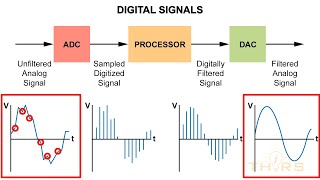
An analog-to-digital converter (ADC) transforms continuous analog signals into discrete digital outputs. For an N-bit ideal ADC with a defined input voltage range from Vmin to Vmax, the resolution is determined as:
$$ \text{LSB} = \frac{V_{max} - V_{min}}{2^N} $$
This resolution indicates how finely the analog input can be segmented. The output digital code corresponding to an input voltage, Vin, is calculated using the formula:
$$ \text{Code} = \left\lfloor \frac{V_{in} - V_{min}}{\text{LSB}} \right\rfloor $$
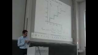
This relationship produces a stair-step characteristic in the ADC’s transfer function which has 2^N levels, indicating the quantization of the input voltage into sets of discrete values. Understanding these transfer functions helps in evaluating precision and accuracy in various ADC applications.
Youtube Videos

Audio Book
Dive deep into the subject with an immersive audiobook experience.
Resolution of an ADC
Chapter 1 of 3
🔒 Unlock Audio Chapter
Sign up and enroll to access the full audio experience
Chapter Content
For an NN-bit ADC with input range VminV_{min} to VmaxV_{max}, the resolution or Least Significant Bit (LSB) size is:
LSB=Vmax−Vmin2N\text{LSB} = \frac{V_{max} - V_{min}}{2^N}
Detailed Explanation
The resolution of an Analog-to-Digital Converter (ADC) is defined by the Least Significant Bit (LSB) size, which indicates the smallest change in voltage that the ADC can detect. For an N-bit ADC with a specific input voltage range (from Vmin to Vmax), the LSB is calculated by taking the total range (Vmax - Vmin) and dividing it by 2 raised to the power of N. The higher the number of bits (N), the smaller the LSB, leading to finer resolution in measuring the analog input signal.
Examples & Analogies
Imagine a measuring tape divided into various sections. If your tape has more markings (higher bits), you can measure smaller lengths more accurately. For instance, a 1-meter tape with 1mm divisions allows you to measure to the nearest millimeter, while a tape with 0.1mm divisions can measure even smaller lengths more precisely.
Output Code Calculation
Chapter 2 of 3
🔒 Unlock Audio Chapter
Sign up and enroll to access the full audio experience
Chapter Content
The output code for an input VinV_{in} is:
Code=⌊Vin−VminLSB⌋\text{Code} = \left\lfloor \frac{V_{in} - V_{min}}{\text{LSB}} \right\rfloor
Detailed Explanation
To determine the digital output code from an analog input voltage (Vin), the ADC uses a conversion formula. The output code is calculated by subtracting the minimum voltage (Vmin) from the input voltage (Vin), dividing this difference by the LSB, and then taking the floor value of the result. This floor function ensures that the output is an integer value, aligning with the discrete nature of digital representations. Thus, the ADC effectively maps the continuous voltage input into a discrete digital code.
Examples & Analogies
Think of a classroom where teachers are measuring students' heights using a ruler marked in whole centimeters. If a student is 157.5 cm tall, the teacher rounds it down to 157 cm (using the floor function) to fit the whole number requirement. Similarly, the ADC takes your continuous input voltage and translates it into the nearest lower whole 'code,' making it suitable for digital processing.
Stair-step Transfer Characteristic
Chapter 3 of 3
🔒 Unlock Audio Chapter
Sign up and enroll to access the full audio experience
Chapter Content
This produces a stair-step transfer characteristic with 2N2^N levels.
Detailed Explanation
When an ideal ADC converts an analog input to a digital code, the resulting relationship between the input voltage and output code forms a staircase-like pattern, which is termed a stair-step transfer characteristic. This characteristic has 2^N discrete levels, reflecting the resolution of the ADC. As the input voltage increases, the output code steps up at each threshold defined by the LSB, which illustrates how the ADC quantizes analog voltages into distinct digital values.
Examples & Analogies
Imagine ascending a staircase in a building. Each step represents a specific height, and at each step, you only change levels when you reach a certain height. In the same way, the ADC only 'jumps' to the next level (or output code) when the input voltage crosses the threshold defined by its resolution (LSB), creating a stair-step profile of output values.
Key Concepts
-
Transfer Function: Defines the relationship between the input and output of the ADC.
-
Resolution: Indicates the smallest change in input that can be represented in the output.
-
Least Significant Bit (LSB): The minimal unit defining the resolution of the ADC.
-
Stair-step Characteristic: The visual form of quantized levels in the ADC's output.
Examples & Applications
An N-bit ADC with a range of 0 to 5V, where N=3. The LSB would be (5V-0V)/2^3 = 0.625V. Therefore, an input of 1.2V would output a digital code of 1 based on the floor calculation.
For an ADC input range of -1V to 1V and N=4 (16 levels), each level would represent 0.25V (resolution), allowing for detailed readings of analog signals.
Memory Aids
Interactive tools to help you remember key concepts
Rhymes
If voltage you wish to see, divide by the LSB, stair-step code will be what we need!
Stories
Imagine climbing stairs representing different voltage levels, each step representing a digital output code, helping you visualize quantization.
Memory Tools
For resolution, remember: Really Significant Bits (RSB), capturing every tiny bit of change!
Acronyms
VRA - Voltage Range Adjustment helps remember the role of Vmin and Vmax in determining LSB.
Flash Cards
Glossary
- Transfer Function
A mathematical representation that relates the output of a system to its input.
- Resolution
The smallest detectable change in an analog signal translated to a digital value.
- Least Significant Bit (LSB)
The smallest unit of data in digital systems, representing the smallest incremental change in value.
- Stairstep characteristic
The visual representation of the quantized output levels of an ADC, resembling steps on a staircase.
- Digital Output Code
The binary number representing the quantized value of the analog input signal.
Reference links
Supplementary resources to enhance your learning experience.