
Examples
Enroll to start learning
You’ve not yet enrolled in this course. Please enroll for free to listen to audio lessons, classroom podcasts and take practice test.
Interactive Audio Lesson
Listen to a student-teacher conversation explaining the topic in a relatable way.
Introduction to Shear and Moment Diagrams
🔒 Unlock Audio Lesson
Sign up and enroll to listen to this audio lesson

Today, we'll explore shear and moment diagrams, which are essential tools for structural analysis. Can anyone tell me what a shear diagram represents?

It shows the internal shear force along the beam.
Exactly! And how does our moment diagram relate to it?

It shows the bending moment along the beam, right?
Correct! Remember, the moment at a section is affected by the shear force, and we can use the diagrams to visualize this relationship.

I heard there's a relationship between the slopes of these curves?
Great observation! The slope of the shear curve corresponds to the load intensity, and the slope of the moment curve corresponds to the shear force. Let's move on to some examples.

Can you show us how to draw these diagrams?
Absolutely! Let's begin with a simple beam example and draw both the shear and moment diagrams together.
Drawing Shear and Moment Diagrams
🔒 Unlock Audio Lesson
Sign up and enroll to listen to this audio lesson

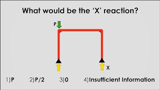
For our first example, we have a simple beam with a point load. Who would like to begin by identifying the shear forces acting on the beam?
The left side of the beam will have a reaction force equal to the load.
That's right! Now, as we move across the beam, how does the shear change?
It drops at the location of the load.
Exactly! Now let's sketch the shear diagram based on these values.
What about the moment diagram? How is it affected?
Good question! The moment diagram is affected by the shear force. A positive area under the shear curve results in a corresponding positive change in the moment. Let's draw that out as well.
This really helps to visualize how forces are transferred in the structure!
More Complex Loading Scenarios
🔒 Unlock Audio Lesson
Sign up and enroll to listen to this audio lesson
Now that we have a grasp on simple beams, let's tackle a more complex scenario presented in Example 6-2. Can someone summarize the loads applied to the beam?
There are multiple point loads and a distributed load!
Great! How do we start sketching the shear and moment diagrams for this case?
We need to first calculate the reactions at the supports and then figure out the shear at different points.
Correct! And various changes in load will affect the shear and moment curves. Let's map these values and draw the diagrams.
It's interesting to see how each load influences the entire structure.
Can we go over how to calculate the area under the curves for these diagrams?
Absolutely! The area under the shear diagram helps us find the moments at the ends. Let's summarize what we’ve learned. We’ve seen how loads, shear, and moments interact across various examples.
Introduction & Overview
Read summaries of the section's main ideas at different levels of detail.
Quick Overview
Standard
The section discusses examples demonstrating the drawing of shear and moment diagrams for beams. It illustrates how to analyze various loading conditions and the resulting diagrams, highlighting the importance of understanding these concepts for structural analysis.
Detailed
Detailed Summary
In this section, we explore various examples related to shear and moment diagrams for beams.
These diagrams are crucial for analyzing structural elements and ensuring their integrity under different loading conditions. The examples include:
- Example 6-1: A simple shear and moment diagram for a beam where students are guided in drawing the shear and moment diagrams for a specific loading case. This foundational example reinforces the understanding of relationships between loads, shear, and moments.
- Example 6-2: Further sketches of shear and moment diagrams that demonstrate various loading scenarios, enhancing students' ability to visualize and interpret different structural conditions.
Through these examples, students learn to apply theoretical concepts from earlier sections, enabling them to determine critical parameters for structural design.
Youtube Videos


Audio Book
Dive deep into the subject with an immersive audiobook experience.
Simple Shear and Moment Diagram
Chapter 1 of 3
🔒 Unlock Audio Chapter
Sign up and enroll to access the full audio experience
Chapter Content
Draw the shear and moment diagram for the beam shown below.
Solution:
The free body diagram is drawn below.
Detailed Explanation
In this chunk, we are required to draw the shear and moment diagrams for a given beam. These diagrams represent how the internal shear and moment change at various points along the beam due to applied loads. A free body diagram serves as a useful tool to visualize and analyze the forces acting on the beam, which will help in drawing correct diagrams.
Examples & Analogies
Think of a beam as a long, flat board balanced on two supports. If you place weights on the board, like putting books on a shelf, you can see how the board bends and where it's stressed the most. Drawing the shear and moment diagrams is like mapping these areas of stress, helping you understand where the board might break.
Sketches of Shear and Moment Diagrams
Chapter 2 of 3
🔒 Unlock Audio Chapter
Sign up and enroll to access the full audio experience
Chapter Content
For each of the following examples, sketch the shear and moment diagrams.
Detailed Explanation
This chunk emphasizes the importance of sketching shear and moment diagrams for various scenarios. Students are encouraged to visualize the internal forces within the beam. By sketching, they can see how the shear force and bending moment vary along the length of the beam and predict potential points of failure or maximum stress.
Examples & Analogies
Imagine you're using a flexible ruler. When you press down at one end, the ruler bends. By sketching the diagrams, you are essentially recording how the ruler bends at different points, which gives you insights into its weaknesses and strengths, just as engineers do with actual structures.
Detailed Example Work
Chapter 3 of 3
🔒 Unlock Audio Chapter
Sign up and enroll to access the full audio experience
Chapter Content
B-C
\( \sum F_x = 0 \) implies \( N_{xB} = 0 \) and \( V_{zC} = -60kN \)
\( \sum F_y = 0 \) implies \( V_{yB} = V_{yC} = +40kN \)
\( \sum M_y = 0 \) implies \( M_{yB} = M_{yC} = -120kN.m \)
\( \sum M_z = 0 \) implies \( M_{zB} = V_{yC}(4) = (40)(4) = +160kN.m \)
\( \sum T_x = 0 \) implies \( T_{xB} = -M_{zC} = -40kN.m \)
... etc.
Detailed Explanation
This chunk presents a detailed calculation for the forces and moments acting on specific sections of the beam. By applying equilibrium equations, students determine forces in the x and y directions, as well as moments about specified points. This analytical process is fundamental in understanding how loads affect structural elements and aids in accurately designing safe and reliable structures.
Examples & Analogies
Picture trying to balance a seesaw. Each kid on either end represents a force acting on the seesaw, and you need to understand how heavy they are to keep it level. In this example, the equations are like the calculations you do to ensure the seesaw doesn’t tip over, helping you maintain the perfect balance.
Key Concepts
-
Shear Forces: The internal forces acting parallel to the section of the beam due to applied loads.
-
Bending Moments: The moments that cause the beam to bend, changing the distribution of internal forces.
-
Shear and Moment Relationships: The connection between shear forces and bending moments along the beam.
Examples & Applications
Example 6-1: Draw the shear and moment diagram for a beam with a single point load.
Example 6-2: Sketch shear and moment diagrams for multiple loading scenarios on beams.
Memory Aids
Interactive tools to help you remember key concepts
Rhymes
Shear is near, it's how forces steer; Moment is the bend, where paths may end.
Stories
Imagine a beam as a gymnast on a balance beam. As weights (loads) are added, they exert force downward, causing shear stress. The gymnast bends and twists (moment) as they dance across.
Memory Tools
SMooth Shear = Slow Momentum: Shear force's slope equals the momentum change.
Acronyms
SMAL (Shear, Moment, Area under Load)
Use this to remember the relationships between the concepts.
Flash Cards
Glossary
- Shear Force
An internal force that acts along the surface of a structural element, resulting in sliding.
- Bending Moment
An internal moment that occurs within a beam or structural element due to external loads, causing it to bend.
- Beam
A long, sturdy piece of squared timber or metal employed to support the structure above it.
- Shear Diagram
A graphical representation showing the variation of shear force along the length of a beam.
- Moment Diagram
A graphical representation of the bending moment along the length of a beam.
Reference links
Supplementary resources to enhance your learning experience.