
INTERNAL FORCES IN STRUCTURES
Enroll to start learning
You’ve not yet enrolled in this course. Please enroll for free to listen to audio lessons, classroom podcasts and take practice test.
Interactive Audio Lesson
Listen to a student-teacher conversation explaining the topic in a relatable way.
Design Sign Conventions
🔒 Unlock Audio Lesson
Sign up and enroll to listen to this audio lesson

Today, we will start by discussing design sign conventions critical for analyzing internal forces in structures. Can anyone explain what a sign convention is?

Is it a way to define which forces are considered positive or negative?
Exactly, Student_1! In our context, a positive load is directed upward along the beam’s local y-axis. Now, can someone tell me what we consider positive for axial tension?

Tension is considered positive.
Correct! And what about flexural moments?

Positive moments cause tension in the lower fibers of the beam.
Great job, everyone! Remembering these sign conventions is key to correctly interpreting our diagrams.
Load, Shear, Moment Relations
🔒 Unlock Audio Lesson
Sign up and enroll to listen to this audio lesson

Let’s dive into load, shear, and moment relationships. If we consider a beam segment experiencing a load w(x), what's our starting point?

We need to apply the equilibrium equations for forces and moments!
Exactly! We start with the equilibrium equation for vertical forces. Can anyone summarize what we derive when we set it up?
We get that dV/dx equals w(x), meaning the change in shear is equal to the load.
Spot on! And for moments, what do we find?
We find that dM/dx equals V(x).
Exactly, Student_2! Keep these relationships in mind as they are foundational for drawing shear and moment diagrams.
Drawing Shear and Moment Diagrams
🔒 Unlock Audio Lesson
Sign up and enroll to listen to this audio lesson
Now that we have discussed the relationships, let’s apply them by drawing shear and moment diagrams for a given beam. Who remembers the general steps?
You start by calculating reactions, then you draw shear based on loads.
Correct! What comes after constructing the shear diagram?
Then, we use the shear diagram to create the moment diagram!
Exactly! Can anyone explain the significance of the areas under the shear diagram?
The areas represent the values of the moment at different points.
Right again! These diagrams are crucial for visualizing how forces are distributed along the beam.
Introduction & Overview
Read summaries of the section's main ideas at different levels of detail.
Quick Overview
Standard
In this section, we review shear and moment diagrams, analyze statically determinate structures, and establish a sign convention for design purposes. Key topics include the relationship between load, shear, and moment, along with practical exercises on drawing shear and moment diagrams.
Detailed
Overview of Internal Forces in Structures
This chapter provides a comprehensive review of the internal forces acting in structures, emphasizing shear and moment diagrams, which are critical for structural analysis and design. We will explore statically determinate frames, arches, and grids, ultimately equipping you with the skills to draw shear, moment, and torsion diagrams for various structural members.
Key Topics
- Design Sign Conventions: Establishing a sign convention helps clarify what constitutes positive and negative forces in structural analysis. The chapter outlines conventions for loads, axial forces, and moments, which impact how shear and moment diagrams are constructed.
- Load, Shear, Moment Relations: The derivation of key relationships between loads, shear forces, and bending moments is fundamental for understanding internal forces in beams. Utilizing infinitesimal segments of beams, we apply equilibrium conditions to derive the differential relationships between these forces.
- Practical Application: We revisit example analyses of beams discussed in earlier chapters, emphasizing the drawing of shear and moment diagrams based on the established relations. Additionally, we will explore how these diagrams are used in member design to ensure safety and compliance with engineering standards.
Youtube Videos


Audio Book
Dive deep into the subject with an immersive audiobook experience.
Introduction to Shear and Moment Diagrams
Chapter 1 of 5
🔒 Unlock Audio Chapter
Sign up and enroll to access the full audio experience
Chapter Content
This chapter will start as a review of shear and moment diagrams which you have studied in both Statics and Strength of Materials, and will proceed with the analysis of statically determinate frames, arches and grids. By the end of this lecture, you should be able to draw the shear, moment and torsion (when applicable) diagrams for each member of a structure.
Detailed Explanation
This chunk introduces the main topics of the chapter: shear and moment diagrams. These diagrams are graphical representations that show how internal forces, like shear forces and bending moments, behave within structural members under different loads. Understanding these diagrams helps us analyze how structures respond to external forces.
Examples & Analogies
Think of a bridge as a long beam. When cars drive over it, they exert forces on the structure. The shear and moment diagrams help us visualize how these forces spread throughout the bridge, similar to how water flows through a pipe. Just as we need to ensure our pipes are suitable for the water pressure, we must ensure our bridge can handle the forces applied to it.
Design Considerations for Beams
Chapter 2 of 5
🔒 Unlock Audio Chapter
Sign up and enroll to access the full audio experience
Chapter Content
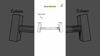
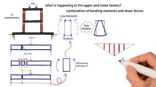
For instance, for flexural design, we will consider the section subjected to the highest moment, and make sure that the internal moment is equal and opposite to the external one.
Detailed Explanation
In structural engineering, when designing beams, it is crucial to ensure that the internal bending moment (the internal force from the material that tries to resist bending) counters the external bending moments (the forces trying to bend the beam). This balance is necessary to prevent failure. The section of the beam that experiences the highest moment is particularly important, as it is where we must ensure sufficient strength.
Examples & Analogies
Imagine pushing down on a ruler that is resting on the edge of a table. The more you push, the more the ruler wants to bend downwards. To keep it steady, you can imagine that the material of the ruler internally pushes back just as hard as you press down. In structural design, we're essentially ensuring that this 'pushing back' is strong enough to handle the pressure.
Sign Conventions for Internal Forces
Chapter 3 of 5
🔒 Unlock Audio Chapter
Sign up and enroll to access the full audio experience
Chapter Content
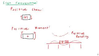
Before we (re)derive the Shear-Moment relations, let us arbitrarily define a sign convention. The sign convention adopted here is the one commonly used for design purposes: Load Positive along the beam’s local y-axis (assuming a right hand side convention), that is positive upward. Axial: tension positive. Flexure A positive moment is one which causes tension in the lower fibers and compression in the upper ones.
Detailed Explanation
Sign conventions are essential in engineering because they establish a uniform way to represent the direction of forces and moments. According to this convention, any load acting upwards is positive, tension (a pulling force) is also positive, and a moment that causes the bottom part of the beam to stretch (tension) is considered positive as well.
Examples & Analogies
Imagine pulling on a rubber band. When you pull it, you cause tension, which we define as 'positive.' Conversely, if you push down on the elastic, you would be compressing it, creating 'negative' tension in our sign convention. This consistency helps engineers communicate clearly about the forces at play.
Load, Shear, and Moment Relations
Chapter 4 of 5
🔒 Unlock Audio Chapter
Sign up and enroll to access the full audio experience
Chapter Content
Let us (re)derive the basic relations between load, shear and moment. Considering an infinitesimal length dx of a beam subjected to a positive load w(x). The infinitesimal section must also be in equilibrium.
Detailed Explanation
This section discusses the mathematical relationships between load, shear, and moment in structures. By analyzing a small segment of a beam (denoted as dx), we can derive equations that link the external load applied to the beam with the internal shear and bending moments. This equilibrium condition ensures that all forces and moments acting on the segment balance out.
Examples & Analogies
Imagine balancing a seesaw. When one side goes down (load applied), the other side (shear and moment) must respond by going up or maintaining balance, depending on where weight is placed. Similarly, in beams, every load creates reactions that need to be analyzed to maintain structural stability.
Differential Equations for Shear and Moment
Chapter 5 of 5
🔒 Unlock Audio Chapter
Sign up and enroll to access the full audio experience
Chapter Content
The slope of the shear curve at any point along the axis of a member is given by the load curve at that point. Similarly, the slope of the moment curve at any point along the axis of a member is given by the shear at that point.
Detailed Explanation
These concepts add depth to our understanding of the relationships between different internal forces. The shear force at a given point in a beam reflects how much the load is applied there, and the moment at a point reflects how that shear force changes along the length of the beam. Mathematically, this relationship is captured through differential equations, allowing us to calculate shear and moment diagrams accurately.
Examples & Analogies
Consider a car driving along a downhill slope. At any moment, the car's speed (akin to shear) depends on how steep the slope (the load) is. The faster the car goes, the sharper it cuts through the slope. The relationship between the car's speed and the slope mimics the relationship between shear and moment in structural analysis.
Key Concepts
-
Shear forces act parallel to surfaces, influencing structural integrity.
-
Bending moments measure rotational effects, critical for beam design.
-
Shear and moment diagrams graphically represent internal forces for analysis.
Examples & Applications
Drawing shear and moment diagrams for a simply supported beam under a uniform load.
Analyzing a cantilever beam and illustrating the shear and moment diagrams.
Memory Aids
Interactive tools to help you remember key concepts
Memory Tools
To recall shear and moment relationships, remember 'Silly Moments Make Shear Strong' where S=Shear, M=Moment.
Rhymes
In a beam where forces play, shear and moment lead the way. Draw them right, keep them neat, for strong designs that won't be beat.
Acronyms
SPLASH - Shear, Positive Load, Axial, Structural Health.
Stories
Imagine a little beam that dreams of supporting a rooftop. It remembers its friends Shear and Moment who guide it in balancing the heavy loads above.
Flash Cards
Glossary
- Shear
A force that acts parallel to the surface of a material.
- Moment
A measure of the tendency of a force to rotate an object about an axis.
- Load Diagram
A graphical representation of loads acting on a beam.
- Shear Diagram
A graphical representation showing how shear forces vary along the length of the beam.
- Moment Diagram
A graphical representation of the bending moment along a structural element.
Reference links
Supplementary resources to enhance your learning experience.