
Sketches of Shear and Moment Diagrams
Enroll to start learning
You’ve not yet enrolled in this course. Please enroll for free to listen to audio lessons, classroom podcasts and take practice test.
Interactive Audio Lesson
Listen to a student-teacher conversation explaining the topic in a relatable way.
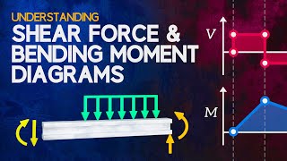
Understanding Shear and Moment Diagrams
🔒 Unlock Audio Lesson
Sign up and enroll to listen to this audio lesson

Today we'll explore shear and moment diagrams. These diagrams help us understand how forces and moments act within a structure. Can anyone tell me why we need to understand these diagrams?

I think they show how loads affect a beam, right?
Exactly! They help us visualize the internal forces caused by external loads. What do you think might happen if we didn't use these diagrams?

We could design structures that fail under load!
Right again! By applying these diagrams, we ensure our designs are safe. Remember, shear and moment diagrams are crucial for ensuring that internal reactions balance external actions.
Sign Conventions in Shear and Moment Diagrams
🔒 Unlock Audio Lesson
Sign up and enroll to listen to this audio lesson

Next, let's discuss sign conventions. Does anyone know what a sign convention is in this context?

I think it's about deciding which directions we say are positive or negative.
Correct! In our context, upward forces are positive. Shear forces causing tension in the lower fibers are also positive. Can anyone give me an example?

If a beam has a load pushing down, then the shear at that point would push upwards on the left side, right?
Exactly! Ensure to keep these conventions in mind; they make drawing these diagrams easier.
Deriving Shear and Moment Relations
🔒 Unlock Audio Lesson
Sign up and enroll to listen to this audio lesson
Let's derive the relationships between load, shear, and moment. Starting from a small segment of beam, what do we have to consider?
We need to think about forces acting on that small piece?
Exactly! We use equilibrium equations. For a positive load w(x), we find dV/dx = w(x). Who can tell me what comes next?
Then we find dM/dx = V(x) because the moment depends on shear!
Perfect! Understanding how these equations connect is fundamental to creating accurate diagrams.
Practical Applications and Examples
🔒 Unlock Audio Lesson
Sign up and enroll to listen to this audio lesson
Now, let's sketch some shear and moment diagrams. Can anyone recall the steps we'll take to do this?
Start with the free body diagram, then calculate reactions, right?
Absolutely! Following that, we plot shear forces and moments along the beam. Who can summarize the process?
We calculate shear at key points, then integrate for moments and sketch them!
Well done! Let's execute an example together.
Introduction & Overview
Read summaries of the section's main ideas at different levels of detail.
Quick Overview
Standard
In this section, the significance of shear and moment diagrams is highlighted with reference to previous analysis studies. The principles of these diagrams are related to the derived relationships between applied loads, shear forces, and bending moments.
Detailed
Sketches of Shear and Moment Diagrams
In engineering, understanding shear and moment diagrams is pivotal. This section builds on previous foundations in statics and strength of materials, describing how shear and moment diagrams are utilized for member design. By the end of the lecture, students should be able to accurately draw these diagrams and apply them to real-world scenarios.
Key Points
- Fundamental Understanding: Shear and moment diagrams represent internal forces and moments within structural members when subjected to loads.
- Sign Convention: A clear sign convention is defined for loads, shear forces, and moments, which helps in visualizing results correctly.
- Integration with Structural Design: Shear and moment diagrams are integral to structural design processes, especially in ensuring that internal forces counteract applied external forces.
- Application in Examples: The section revisits specific examples, highlighting how to generate and interpret these diagrams accurately, which is vital for analyzing structures effectively.
Youtube Videos


Audio Book
Dive deep into the subject with an immersive audiobook experience.
Introduction to Shear and Moment Diagrams
Chapter 1 of 3
🔒 Unlock Audio Chapter
Sign up and enroll to access the full audio experience
Chapter Content
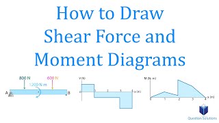
For each of the following examples, sketch the shear and moment diagrams.
Detailed Explanation
In this section, we will focus on how to sketch shear and moment diagrams based on given examples. These diagrams help visualize how shear forces and bending moments vary along the length of a beam. Understanding these concepts is crucial in structural engineering as they play a significant role in the design and safety of structures.
Examples & Analogies
Imagine you are driving down a mountain road. The steepness of the road represents the changes in shear and moment diagrams. Just like you may feel your vehicle tilting more on steep parts, the shear and moment in a beam change depending on the loads it carries and supports it encounters.
Sketching Shear Diagrams
Chapter 2 of 3
🔒 Unlock Audio Chapter
Sign up and enroll to access the full audio experience
Chapter Content
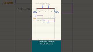
Sketch the shear diagrams based on the given load positions and magnitudes.
Detailed Explanation
To sketch the shear diagram, identify the points where loads are applied, including concentrated loads and support reactions. Start at one end of the beam and calculate the shear force at intervals along the beam's length. The shear diagram will typically consist of horizontal lines (indicating constant shear) and vertical jumps (indicating changes due to loads).
Examples & Analogies
Think of the shear force like the pressure you feel on your hands when pushing down on a table. If someone places a heavy box on the table (like applying a load), you will feel an increase in pressure at the spot where it's placed, similar to how the shear diagram 'jumps' where the load is located.
Sketching Moment Diagrams
Chapter 3 of 3
🔒 Unlock Audio Chapter
Sign up and enroll to access the full audio experience
Chapter Content
Sketch the moment diagrams based on the previously sketched shear diagrams.
Detailed Explanation
To create the moment diagram, start by calculating the bending moments at specific points along the beam, using the area under the shear diagram. The moment diagram will consist of curves that represent the cumulative effects of shear along the beam. Positive moments typically indicate bending that causes the bottom fibers of the beam to experience tension, while negative moments induce compression in the top fibers.
Examples & Analogies
Imagine bending a ruler: the point where you apply the most force causes it to bend most dramatically. The moments in the diagram show us where the biggest 'bends' will be in the beam, just like in bending the ruler where it flexes most.
Key Concepts
-
Shear Force: The component of force that acts on a beam's cross-section.
-
Bending Moment: The moment that results in the bending of a beam due to external loads.
-
Sign Convention: A standardized method for designating positive and negative directions for forces and moments.
-
Equilibrium: The state in which all external forces and moments are balanced.
Examples & Applications
Example 1: Consider a simply supported beam with a uniform load. The shear diagram shows linear variation, while the moment diagram is parabolic.
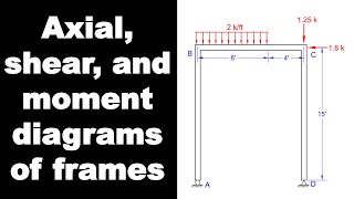
Example 2: In a cantilever beam, an upward point load causes a constant negative shear and a linear moment diagram that peaks at the wall.
Memory Aids
Interactive tools to help you remember key concepts
Rhymes
In beams, when forces do combine, shear goes up and moment's fine.
Stories
Imagine a beam that feels heavy loads from above—it bends and hugs its lower side, while pushing back with all its might.
Memory Tools
S-M-L: S for Shear, M for Moment, L for Load. Remember the connections!
Acronyms
SPIN
Shear Positive
Internal Negative for clear direction understanding.
Flash Cards
Glossary
- Shear Force
An internal force that acts along the cross-section of a structural element.
- Bending Moment
An internal moment that induces curvature in a structural element.
- Sign Convention
A standard method of determining the positive and negative directions for forces and moments.
- Free Body Diagram
A graphical representation showing all forces acting on a free segment of a structure.
Reference links
Supplementary resources to enhance your learning experience.