
Effect of Collector Terminal Resistance
Enroll to start learning
You’ve not yet enrolled in this course. Please enroll for free to listen to audio lessons, classroom podcasts and take practice test.
Interactive Audio Lesson
Listen to a student-teacher conversation explaining the topic in a relatable way.
Introduction to Common Collector Amplifiers
🔒 Unlock Audio Lesson
Sign up and enroll to listen to this audio lesson

Today, we will explore common collector amplifiers, focusing on their behavior with the introduction of collector terminal resistance. Can anyone define a common collector amplifier and its main characteristics?

I think a common collector amplifier is one where the output is taken from the emitter, making it a voltage follower.
That's correct! The main characteristic is that it provides high input resistance and low output resistance. Now, how does introducing collector terminal resistance impact these characteristics?

Does it lower the input resistance?
Good thought! It modifies the resistance slightly but doesn't significantly lower it. Remember, input resistance remains high due to the transistor's configuration. Let's explore how we mathematically analyze the effects of this resistance.
Analyzing Voltage Gain with Collector Resistance
🔒 Unlock Audio Lesson
Sign up and enroll to listen to this audio lesson

Now let's talk about voltage gain. How do we generally compute voltage gain for a common collector amplifier?

Isn't it usually close to 1?
Exactly! Without considering resistances, it's almost unity. However, what happens when we incorporate collector resistance, R_L?

Does it change the gain significantly?
It modifies the gain expression, but due to the high value of R_L, the gain still approximates to 1 in practical scenarios. Utilizing our analytical skills is key here!
Effects on Input and Output Resistance
🔒 Unlock Audio Lesson
Sign up and enroll to listen to this audio lesson
Next up, let's delve into how input and output resistance are affected. Who can explain our approach to calculating these resistances?
We look at the internal resistances in the circuit and how they interact, right?
Correct! For output resistance, we need to consider the parallel combination of various components including R_L. Remember, R_L's influence becomes critical in some contexts. What conclusions can we draw regarding practical circuit design?
I think the design still expects high input and low output resistances, with R_L playing a secondary role?
Well put! Maintaining high input resistance is paramount. Just remember, additional resistances introduce slight modifications but fundamental amplifier properties remain.
Application of the Concepts in Common Drain Amplifiers
🔒 Unlock Audio Lesson
Sign up and enroll to listen to this audio lesson
Let’s shift our focus to common drain amplifiers. How do they differ from common collector amplifiers in terms of resistance effects?
Common drain amplifiers also have high input resistance, right? But the structure is different?
Exactly! While the resistance concepts carry over, the absence of certain elements modifies our approach slightly. Anyone want to summarize the effects of introducing resistance in both amplifier types?
Without significant loss of performance! It's about maintaining core characteristics while understanding nuanced differences.
Great synthesis! Keep these principles in your toolkit as we continue to analyze more complex circuits.
Introduction & Overview
Read summaries of the section's main ideas at different levels of detail.
Quick Overview
Standard
The section delves into the practical implications of including collector terminal resistance in common collector and common drain amplifiers, exploring how it affects voltage gain, input resistance, and impedances while maintaining the core characteristics of the amplification process. It emphasizes analysis both with and without resistance components, enhancing overall understanding.
Detailed
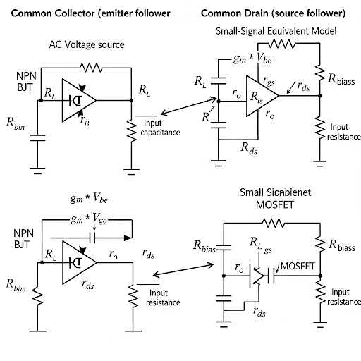
In this section, we explore the effect of collector terminal resistance on common collector and common drain amplifiers. We begin with the basic operation of a common collector amplifier, including small signal equivalent circuits and the introduction of various resistance components (like R_L—load resistance and R_bias—bias circuit resistance). The analysis focuses on how the collector terminal resistance affects the voltage gain, input capacitance, and input resistance. We illustrate that while adding collector terminal resistance modifies the derived expressions, key amplifier characteristics—such as high input resistance and low voltage gain—are largely retained. Additionally, we find that output resistance computations still follow the same trend, reflecting the dominance of certain components over others. The section also briefly touches on analyzing the common drain amplifier under similar considerations, driving home the conclusion that even in the presence of additional resistance, primary amplifier functions remain intact.
Youtube Videos

Audio Book
Dive deep into the subject with an immersive audiobook experience.
Introduction to Collector Terminal Resistance
Chapter 1 of 5
🔒 Unlock Audio Chapter
Sign up and enroll to access the full audio experience
Chapter Content
So, to start with let we let you consider the common collector amplifier and also in the common collector amplifier we are including this R_c. So, this R_c may be coming from the bias circuit, representing the finite conductance of the bias circuit or maybe and/or maybe additional load resistance we are connecting at the output node with respect to ground.
Detailed Explanation
The chunk introduces the common collector amplifier and includes the importance of the collector terminal resistance (R_c). This resistance can come from a biasing circuit or it can be a load resistance added to the output. Understanding this component is crucial because it can affect the performance and characteristics of the amplifier.
Examples & Analogies
Think of an amplifier like a water pipe. The water flowing represents the electrical signal; R_c acts like a restriction in the pipe which can slow down the water flow. Depending on where you place that restriction, it will either improve or hinder the flow, just as R_c can impact the amplifier's efficiency.
Small Signal Equivalent Circuit
Chapter 2 of 5
🔒 Unlock Audio Chapter
Sign up and enroll to access the full audio experience
Chapter Content
So, whatever it is let you consider this R_c in our analysis and here we do have small signal equivalent circuit of the common collector amplifier having this R_c included.
Detailed Explanation
This chunk highlights the role of the small signal equivalent circuit in analyzing the common collector amplifier with the introduction of collector terminal resistance R_c. The small signal model simplifies the understanding of how signals behave when small changes occur in the circuit, making analysis more straightforward.
Examples & Analogies
Imagine a car's suspension system. Small bumps in the road don't significantly change the overall journey, but understanding how the suspension reacts to those bumps (small signals) helps in designing a smoother ride. In electronics, the small signal equivalent circuit allows us to see how minor changes impact circuit behavior.
Impact on Voltage Gain and Input Capacitance
Chapter 3 of 5
🔒 Unlock Audio Chapter
Sign up and enroll to access the full audio experience
Chapter Content
So, in our previous analysis where we have excluded this R_c there we have seen the expression of the input capacitance. Basically, the input capacitance at the base with respect to the AC ground.
Detailed Explanation
This section discusses how excluding the collector terminal resistance affects the derived expressions for voltage gain and input capacitance. The analysis shows that when R_c is considered, the input capacitance changes and thus alters voltage gain calculations, illustrating how component values can affect overall circuit performance.
Examples & Analogies
Consider a team of people trying to lift a heavy object. If one person (R_c) becomes weak, the whole group (the amplifier) may not lift the object (signal) as effectively. Similarly, the voltage gain changes based on how effective the resistances are in the circuit.
Simplifying Assumptions for Analysis
Chapter 4 of 5
🔒 Unlock Audio Chapter
Sign up and enroll to access the full audio experience
Chapter Content
So, wherever we do have the you may replace this by beta (β) of the transistor. So, here also we can write this is ( )(1- A) ≈ C.
Detailed Explanation
This chunk addresses the simplifications made during analysis by substituting parameters like beta (β) in the expressions for input capacitance and voltage gain. These approximations make calculations more manageable while still providing useful insights into circuit behavior.
Examples & Analogies
Imagine a linguist trying to understand a new language. Rather than learning every single word, they might focus on the most common verbs and nouns to communicate effectively. Similarly, engineers use simplifications to understand complex circuits without getting lost in details.
Final Effects on Amplifier Performance
Chapter 5 of 5
🔒 Unlock Audio Chapter
Sign up and enroll to access the full audio experience
Chapter Content
So, the bottom line is that even if I consider R_c, the main property of the input resistance to be high, voltage gain it is close to 1, input capacitance is very small defined by C.
Detailed Explanation
The concluding insights summarize the overall findings related to the collector terminal resistance. Despite including R_c, the amplifier retains its fundamental features such as high input resistance, a voltage gain close to 1, and a small input capacitance, which are desirable in amplifier design.
Examples & Analogies
Think about a well-designed bridge that can support heavy traffic without wobbling. Even if you add some decorations (R_c), the bridge maintains its structural integrity (voltage gain and input resistance). Similarly, the common collector amplifier remains effective even with practical adjustments like R_c.
Key Concepts
-
Input Resistance: The resistance seen by the input signal, ideally high to minimize signal loading.
-
Voltage Gain: The ratio of the output voltage to the input voltage; typically approximates to 1 in a common collector configuration.
-
Collector Terminal Resistance: Resistance affecting performance metrics when included in amplifier analysis.
Examples & Applications
Example of calculating voltage gain by modifying standard equations with R_L in place.
Use of small signal equivalent circuit to derive input and output resistance when R_L changes.
Memory Aids
Interactive tools to help you remember key concepts
Rhymes
In the collector, resistance is king, it modifies gains; that’s the thing.
Stories
Imagine a conductor in a copper wire, each resistance adds a layer, to the amplifier's choir.
Memory Tools
R-V-I: Remember Voltage is Input - a reminder that gain equals close to unity!
Acronyms
C.R.A.F.T. – Collector Resistance Affects Functionality Theory.
Flash Cards
Glossary
- Common Collector Amplifier
An amplifier configuration where the output is taken from the emitter, effectively acting as a voltage follower.
- Collector Terminal Resistance (R_L)
The resistance seen at the collector terminal affecting amplifier performance metrics.
- Voltage Gain
The ratio of output voltage to input voltage, often close to 1 in common collector configurations.
- Input Impedance
The resistance faced by the input signal, ideally should be high in amplifiers.
- Output Resistance
The resistance provided at the output; a lower value is typically desired in amplifiers.
Reference links
Supplementary resources to enhance your learning experience.