
Source Resistance Considerations
Enroll to start learning
You’ve not yet enrolled in this course. Please enroll for free to listen to audio lessons, classroom podcasts and take practice test.
Interactive Audio Lesson
Listen to a student-teacher conversation explaining the topic in a relatable way.
Voltage Gain and Input Capacitance
🔒 Unlock Audio Lesson
Sign up and enroll to listen to this audio lesson

Today, we will start by understanding the voltage gain of a common collector amplifier when we include a source resistance, R_s. Can anyone tell me why we consider source resistance in real circuits?

We consider source resistance because in real amplifiers, the input signal may have some resistance due to the source.
Exactly! Now, when we account for R_s, the voltage gain A, as defined previously, approximates to close to 1, but why do we assume that?

It's because the input resistance of the amplifier is usually very high compared to R_s.
Correct! So, the effect of R_s on the voltage gain is relatively small. What about the input capacitance? How does R_s affect that?

The input capacitance includes contributions from the internal parasitic capacitances and behaves similarly regardless of R_s.
Right! So, when we calculate input capacitance, we still primarily look at the parasitic elements contributing significantly.
To summarize, the voltage gain remains close to 1 with the presence of source resistance, and the input capacitance is influenced more by internal capacitive effects than R_s.
Output Resistance
🔒 Unlock Audio Lesson
Sign up and enroll to listen to this audio lesson

Let’s dive deeper into output resistance. Who can describe how we evaluate output resistance in the common collector stage?

We look at the total conductance from all elements contributing and calculate its reciprocal to find output resistance.
Very good! Now, when we include R_s, what should we be careful about in terms of its value compared to the internal resistances?
If R_s is high, it can significantly modify the overall output resistance.
Yes! So you understand that R_s should be factored in with careful consideration for accurate circuit design. Always keep in mind its relative size compared to other resistances in the circuit.
In summary, output resistance is determined by the reciprocal of total conductance, and the presence of R_s could influence this depending on its relative value.
Practical Applications and Resistance Modeling
🔒 Unlock Audio Lesson
Sign up and enroll to listen to this audio lesson
Let’s relate our learning to practical applications. How do you think the concepts we've discussed get applied in designing real circuits?
We need to carefully choose components, considering their resistances to ensure the amplifier performs efficiently.
Absolutely! For example, what happens when we try to connect devices with significantly different resistances?
We could potentially load down the circuit, affecting both the voltage gain and input/output resistances.
Correct! Matching impedances between stages often maximizes performance. Always remember to evaluate all resistances at play.
In conclusion, the proper modeling and consideration of source and terminal resistances are vital for effective amplifier design.
Introduction & Overview
Read summaries of the section's main ideas at different levels of detail.
Quick Overview
Standard
The section delves into the implications of including source resistance in common collector and common drain amplifiers. It addresses how this resistance affects input and output resistance, voltage gain, and capacitance while also highlighting the significance of considering practical circuit elements during analysis.
Detailed
In this section, we explore the considerations related to source resistance in common collector and common drain amplifiers within analog electronic circuits. We start by discussing the fundamental principles of these amplifiers, followed by an analysis of how various resistances, including source resistance, impact their performance.
The common collector amplifier's voltage gain, input impedance, and capacitance are examined thoroughly with and without source resistance in play. The teacher introduces the concept of resistance in practical bias circuits, acknowledging how these resistances can be accounted for using small signal equivalent circuits.
We also analyze how the addition of source resistance affects the overall performance metrics of the amplifier. In each case, simplifications are made under the assumption of very high or negligible values, which leads to approximate conclusions about the amplifier's behavior. The ultimate takeaways include understanding that, despite the introduction of additional resistances, key amplifier characteristics such as high input resistance and voltage gains close to 1 are generally maintained.
Youtube Videos

Audio Book
Dive deep into the subject with an immersive audiobook experience.
Impact of Source Resistance in Common Collector Amplifier
Chapter 1 of 4
🔒 Unlock Audio Chapter
Sign up and enroll to access the full audio experience
Chapter Content
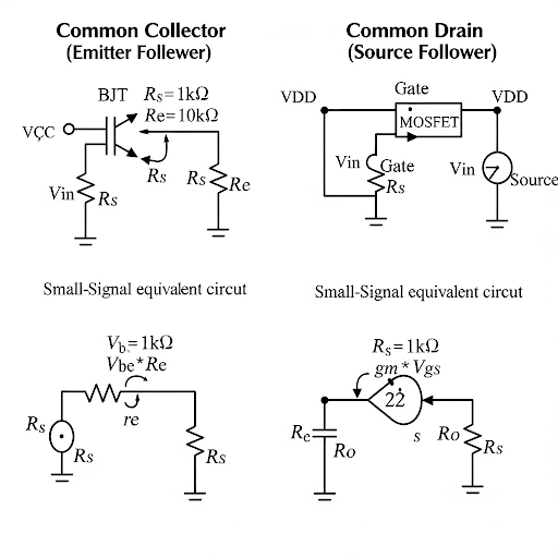
So, let us see the common collector amplifier considering this source resistance, signal source resistance. We do have the circuit given here. So, we are considering this source resistance R_s. Again, R_L we are ignoring, so we are considering one effect at a time. And then the small signal model of this circuit is given here and of course, we should have considered the signal here. Now this supposed to be the output v_o. Now, what are the parameters we need to consider, the voltage gain? Input resistance, then output resistance, and then C_in.
Detailed Explanation
In this chunk, we start by discussing the role of source resistance (R_s) in the context of the common collector amplifier. It explains that while analyzing the circuit with the source resistance, other factors are momentarily ignored for clarity. The small signal model is introduced, emphasizing the importance of assessing voltage gain, input resistance, output resistance, and input capacitance. This sets the stage for a deeper analysis of how source resistance affects the overall performance of the amplifier.
Examples & Analogies
Think of a faucet in a plumbing system where the water flow represents signal flow. If you place a tap (the source resistance R_s) very close to the faucet, you may notice that the amount of water reaching the garden hose (output) is affected. In this analogy, the faucet represents the amplifier, the water flow corresponds to the signal, and the tap is like the source resistance that modifies how much signal reaches the output.
Output Resistance with Source Resistance Considered
Chapter 2 of 4
🔒 Unlock Audio Chapter
Sign up and enroll to access the full audio experience
Chapter Content
Now, to get the source resistance sorry the output resistance of this circuit, what you have to do? We need to stimulate the circuit by say v_x and we need to observe the corresponding current here i_x. So, before we go into the i expression, we need to make the voltage, the signal here it is 0, so that is why you are making this is AC ground and if we apply v_x here, the voltage coming at the base to emitter terminal, so between base to emitter terminal what we have it is v_be.
Detailed Explanation
In this chunk, the process of determining the output resistance of the common collector amplifier with the source resistance is elaborated. It begins with the application of an input voltage (v_x) while grounding the AC component to isolate the output parameters. The importance of analyzing voltage across the base-emitter terminals (v_be) is highlighted. The current through the active device (i) is discussed in terms of how to calculate the overall output resistance based on the conditions applied (grounding) and the resulting contributions of various circuit elements.
Examples & Analogies
Consider a series of pumps connected in order, where each pump must push the water through before it reaches the final destination (the output). To measure how hard the last pump has to work, you might temporarily seal off the water flowing backwards and check the pressure difference at each pump. Just like the pumps, the output resistance in this circuit is being determined while isolating and carefully calculating the effect of the source resistance on the overall flow (current).
Voltage Gain Considerations
Chapter 3 of 4
🔒 Unlock Audio Chapter
Sign up and enroll to access the full audio experience
Chapter Content
Now, if you see here most of the time this R_s as I said R_s is very high. So, this factor whole factor it is approximately 1.
Detailed Explanation
This segment explains that voltage gain is primarily influenced by the source resistance (R_s). Given that R_s is generally high, it leads to the overall realization that its effect can be neglected under normal conditions, thus approximating the voltage gain factor as 1. This emphasizes the robustness of the common collector amplifier in maintaining gain despite variations in source resistance, confirming its buffering capabilities.
Examples & Analogies
Imagine you are listening to music through headphones while walking in a busy street. The background noise represents variations in source resistance. Even though there's a lot of noise, your headphones (the common collector amplifier) continue delivering almost the same quality of sound (output voltage), as they are well-designed to filter out background disturbances, akin to how a high R_s maintains an effective voltage gain.
Overall Circuit Behavior
Chapter 4 of 4
🔒 Unlock Audio Chapter
Sign up and enroll to access the full audio experience
Chapter Content
Now, that is about the common collector amplifier if you consider its counterpart mass counterpart namely the common drain stage and then if you consider this R_L for that, what you will be getting it is similar kind of things we can get only difference is that this r_π, it will be it will not be there.
Detailed Explanation
Here, the discussion shifts to the comparison of the common collector amplifier with the common drain stage. It notes that while the influence of the respective source resistance (R_L) is similarly observed, the absence of r_π in the common drain stage suggests that certain performance metrics remain unchanged. This indicates a consistency in the general principles governing both amplifier types, affirming the practical understanding of source resistance's role in audio amplification.
Examples & Analogies
Think about two different types of musical instruments: an electric guitar (common collector) and a keyboard (common drain). While they both produce sound, the electric guitar requires an amplifier due to its inherent resistance to sound clarity, whereas the keyboard automatically delivers clear tones without needing much adjustment. This shows how even when one instrument might demand more attention (source resistance), both instruments effectively serve their purpose in delivering quality sound.
Key Concepts
-
Source Resistance: Affects the input and output properties of amplifiers.
-
Voltage Gain: Tends to approximate to 1 in common collector configurations even with source resistance.
-
Input Capacitance: Primarily defined by internal capacitances rather than R_s.
-
Output Resistance: Influenced by overall conductance, particularly in the presence of R_s.
Examples & Applications
When designing a common collector amplifier, engineers often account for a source resistance of 10kΩ to determine how much signal loss may occur.
In practical applications, high input resistance is crucial to prevent loading down the source signal that would otherwise distort the intended output.
Glossary
- Common Collector Amplifier
An amplifier configuration where the output is taken from the emitter; characterized by high input impedance and low output impedance.
- Source Resistance (R_s)
The resistance present in the signal source which may influence the input characteristics of the amplifier.
- Voltage Gain (A)
The ratio of output voltage to input voltage in an amplifier.
- Input Capacitance
The total capacitance at the input terminal of the amplifier, including parasitic capacitance.
- Output Resistance
The resistance looking back into the output of the amplifier; critical for determining its ability to drive loads.
Reference links
Supplementary resources to enhance your learning experience.