
Introduction
Enroll to start learning
You’ve not yet enrolled in this course. Please enroll for free to listen to audio lessons, classroom podcasts and take practice test.
Interactive Audio Lesson
Listen to a student-teacher conversation explaining the topic in a relatable way.
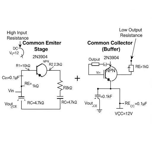
Limitations of Common Emitter and Common Source Amplifiers
🔒 Unlock Audio Lesson
Sign up and enroll to listen to this audio lesson

Let's begin with understanding the limitations of common emitter and common source amplifiers. Can anyone tell me what issues might arise when cascading two of these amplifiers together?

I think one problem is that the output of the first amplifier can load the input of the second.
Exactly! This loading effect can degrade the signal quality we want to pass through. Can anyone explain how it impacts voltage gain?

If the output resistance of the first stage is high and the input resistance of the second is low, some of the signal gets divided, reducing gain.
Great insight! This signal division is a crucial factor in getting less voltage gain. We need to look for a solution, and that’s where common collector and common drain amplifiers come in.
Introduction to Buffers
🔒 Unlock Audio Lesson
Sign up and enroll to listen to this audio lesson

To tackle the loading effects we just discussed, we can introduce a buffer. Who can explain the role of a buffer amplifier?

A buffer amplifier has a very high input resistance and a low output resistance, which prevents the signal from being affected by loading.
Exactly! It acts as a protective layer between stages. So, when we talk about common collector and common drain amplifiers, they effectively serve as such buffers. Can anyone summarize the characteristics we want from these configurations?

We want high input resistance, low output resistance, low input capacitance, and ideally a voltage gain close to 1.
Perfect summary! These configurations really help in preserving signal strength during cascaded operations.
Performance Metrics of Common Collector and Drain Configurations
🔒 Unlock Audio Lesson
Sign up and enroll to listen to this audio lesson
Now, let us focus on the performance metrics for our new configurations. What would you say are some important metrics we should consider?
We should look at the output resistance, input resistance, input capacitance, and voltage gain.
Absolutely! Why are these metrics particularly important when we are dealing with cascaded stages?
Keeping those metrics optimized ensures that the overall performance remains intact, minimizing degradation.
Excellent point! With these fundamentals set, we can have a strong basis for understanding individual operation, biasing, and analysis of the common collector and common drain amplifiers.
Introduction & Overview
Read summaries of the section's main ideas at different levels of detail.
Quick Overview
Standard
The section discusses the motivation behind using common collector and common drain amplifiers in analog electronic circuits. It highlights the limitations of common emitter and common source amplifiers when cascading stages and introduces key performance metrics for the new configurations, setting the stage for deeper analysis of their basic operation and biasing methods.
Detailed
Detailed Summary
In this section, we are introduced to Common Collector and Common Drain Amplifiers, two important configurations in analog electronic circuits. The instructor, Prof. Pradip Mandal from IIT Kharagpur, begins by welcoming students and contextualizing the lesson within their overall course on Analog Electronic Circuits. The primary motivation for discussing these new configurations is illustrated through their significant advantages over more traditional Common Emitter (CE) and Common Source (CS) amplifiers, especially when cascading multiple amplifier stages.
Key points covered include:
- Limitations of Traditional Configurations: The common emitter and common source amplifiers can suffer from reduced voltage gain and bandwidth when their outputs are directly connected to the inputs of subsequent stages due to their loading effects illustrated through small signal models.
- Introduction of Buffers: The necessity of adding buffers into amplifier circuits is explored. Common collector and common drain amplifiers serve as buffers that protect the preceding amplifier's performance by maintaining high input resistance and low output resistance, thus preserving signal integrity.
- Performance Metrics: The section covers essential performance metrics for the new configurations: high input resistance, low output resistance, low input capacitance, and a voltage gain approximately equal to 1, which minimizes voltage attenuation.
The section concludes with the recommendation that these new amplifier configurations will lead to improved performance in cascading applications, laying the groundwork for further discussions on their operational principles and circuit analysis in subsequent lectures.
Youtube Videos

Audio Book
Dive deep into the subject with an immersive audiobook experience.
Overview of Common Collector and Common Drain Amplifiers
Chapter 1 of 5
🔒 Unlock Audio Chapter
Sign up and enroll to access the full audio experience
Chapter Content
Today’s topic of discussion it is Common Collector and Common Drain Amplifiers. Based on our overall flow let us see where we stand. We are in week-5 and we are discussing about the building blocks, specifically we are going to discuss as I said common collector amplifier and common drain amplifiers.
Detailed Explanation
In this introduction, we are presented with the topic of Common Collector and Common Drain Amplifiers. This is part of a larger course on Analog Electronic Circuits, indicating it’s crucial for students to understand these configurations as basic building blocks in electronics. We are currently in week 5 of the course, where deeper concepts of amplifier design and operation are tackled.
Examples & Analogies
Think of amplifiers like a water pump. The Common Collector and Common Drain configurations are distinct types of pumps, each suited for specific tasks—some pumps push water up (just like amplifiers can boost signals), while others ensure that water can easily flow without much pressure loss.
Motivation for New Configurations
Chapter 2 of 5
🔒 Unlock Audio Chapter
Sign up and enroll to access the full audio experience
Chapter Content
Let us see what the basic motivation is, rather let we try to recapitulate whatever the discussion we had in the previous class. Namely, what are the limitations it was there for common emitter and common source amplifier specifically when we are cascading say two stages by connecting output of the one CE amplifier to the input of the next CE amplifier.
Detailed Explanation
Here, the focus is on understanding the limitations faced when cascading Common Emitter (CE) and Common Source (CS) amplifiers. It's highlighted that connecting the output of one amplifier to the input of another can result in signal degradation. This is primarily due to the interaction of the input resistance and output resistance between stages, leading to lower voltage gain in the cascaded setup.
Examples & Analogies
Imagine trying to pour water from one container into a smaller opening of another—if the first container pushes water too fast and the second can’t handle it, water spills everywhere. Similarly, in electronics, amplifiers need to be well-matched to ensure signals transfer without losing strength.
Buffer as a Solution to Limitations
Chapter 3 of 5
🔒 Unlock Audio Chapter
Sign up and enroll to access the full audio experience
Chapter Content
What is the solution for that? It is we can use a buffer in between these two circuits and if you have some specific buffer protecting the previous stage of the first stage from the loading effect coming from the second stage.
Detailed Explanation
To address the limitations mentioned earlier, the introduction of a buffer circuit is proposed. A buffer minimizes the loading effect—the reduction of signal strength caused by the input impedance of the subsequent stage. By doing so, the original signal from the first stage remains intact when it reaches the second stage, leading to improved performance.
Examples & Analogies
Consider a concert where a powerful band is playing; the sound needs to reach the audience clearly. A buffer, like well-placed speakers, distributes the sound effectively without overwhelming or distorting the music. In electronics, a buffer boosts the signal before it reaches another stage, preserving its quality.
Performance Parameters of Buffers
Chapter 4 of 5
🔒 Unlock Audio Chapter
Sign up and enroll to access the full audio experience
Chapter Content
So, what we are looking for is as we said that the input resistance to be high, output resistance should be small, then input capacitance should be small, that is getting obtained from different configuration.
Detailed Explanation
The essential characteristics for an effective buffer include high input resistance, low output resistance, and minimal input capacitance. High input resistance ensures that the buffer does not draw significant current from the previous stage, while low output resistance helps deliver the maximum signal to the next stage. These parameters are critical to maintaining signal integrity in cascaded amplifiers.
Examples & Analogies
Think of a high-efficiency battery charger. A charger must absorb minimal energy while maximizing power output to charge the battery quickly without draining it. Similarly, an effective buffer should draw low current (high input resistance) and supply sufficient voltage while introducing minimal delay (low output resistance).
Overview of Goals
Chapter 5 of 5
🔒 Unlock Audio Chapter
Sign up and enroll to access the full audio experience
Chapter Content
So, this is the summary of that. Just know what we said is we are looking for this buffer circuit particularly for voltage mode amplification, and the important performance matrices.
Detailed Explanation
The conclusion drawn summarises the goals regarding the use of buffer circuits in amplifiers. Specifically, performance matrices such as low output resistance, high input resistance, and minimal voltage attenuation are critical to achieving effective voltage mode amplification. These parameters shape the design and application of common collector and common drain configurations.
Examples & Analogies
When planning a journey, a good route will minimize stops, maintain a steady speed, and ensure you arrive at your destination without delays—similarly, buffers in amplifiers aim to ensure signals travel efficiently without unnecessary loss or degradation.
Key Concepts
-
High Input Resistance: This allows the amplifier to accept a signal without significantly loading the previous stage.
-
Low Output Resistance: This ensures that the amplifier can drive the next stage effectively without signal degradation.
-
Voltage Gain ≈ 1: Indicates minimal signal attenuation between stages.
-
Cascading Amplifiers: Refers to connecting multiple amplifier stages for greater overall gain.
Examples & Applications
In audio systems, common collector amplifiers act as buffers to prevent signal loss between different processing stages.
Common drain amplifiers are used in RF amplifiers to maintain high fidelity and efficiency when connecting multiple stages.
Memory Aids
Interactive tools to help you remember key concepts
Rhymes
In a circuit that's keen, a buffer's unseen, high input, low output, keeps signals clean.
Stories
Imagine a relay race where a runner (the signal) passes the baton (stage) without losing speed (voltage gain), the relay station (buffer) ensures they don’t slow down.
Memory Tools
Remember BAIL: Buffer, Amplifier, Input, Low-output for understanding the roles in common collector and drain configurations.
Acronyms
Remember H I L I
High Input
Low Output
Ideal buffer to keep the flow.
Flash Cards
Glossary
- Common Collector Amplifier
A type of BJT amplifier configuration that provides high input resistance and low output resistance.
- Common Drain Amplifier
A MOSFET amplifier configuration that also features high input resistance and low output resistance.
- Buffer Amplifier
An amplifier that isolates the input and output stages by providing a high input impedance and low output impedance.
- Voltage Gain
The ratio of output voltage to input voltage in an amplifier.
- Cascading
Connecting multiple amplifiers in series where the output of one amplifier feeds the input of the next.
- Loading Effect
The reduction in output voltage of an amplifier due to the impedance of the load it is driving.
Reference links
Supplementary resources to enhance your learning experience.