
CMOS Logic Gates Recap
Enroll to start learning
You’ve not yet enrolled in this course. Please enroll for free to listen to audio lessons, classroom podcasts and take practice test.
Interactive Audio Lesson
Listen to a student-teacher conversation explaining the topic in a relatable way.
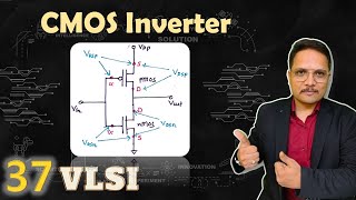
CMOS Inverter
🔒 Unlock Audio Lesson
Sign up and enroll to listen to this audio lesson

Let's begin with the CMOS inverter. Can anyone tell me what an inverter does?

The inverter outputs the opposite of the input signal!
Exactly! So if we put in a high signal, what happens to the output?

The output becomes low!
Correct! Remember this function as the 'Inverse Inverter.' Also, think of it as a simple toggle — input high, output low, and vice versa.

Is it common in circuits?
Very common! It's a fundamental building block for more complex gates. Let's summarize: a CMOS inverter outputs the opposite signal of its input.
Universal Gates (NAND and NOR)
🔒 Unlock Audio Lesson
Sign up and enroll to listen to this audio lesson

Now, let's look at NAND and NOR gates. Why do you think they're called universal gates?
Because we can build any logic gate using them?
Correct! The NAND gate outputs low only when all inputs are high. Can anyone provide the truth table for a NAND gate?

Sure! It's 1, 1, 1, 0 for inputs 0,0; 0,1; 1,0; and 1,1 respectively.
Perfect! Now what about the NOR gate?
It only outputs high when both inputs are low!
Exactly! Both NAND and NOR gates are pivotal in designing complex circuits. Let's conclude this session with a summary: Both gates allow the construction of any other logic gate.
XOR and XNOR Gates
🔒 Unlock Audio Lesson
Sign up and enroll to listen to this audio lesson
Let's move on to the XOR gate. Can anyone tell me its function?
It outputs high when one input is high and the other is low.
Well put! It's crucial for applications like arithmetic operations. How would you remember its function?
By thinking 'exclusive' — it’s exclusive to situations where the inputs differ.
Great mnemonic! Now the XNOR gate — who can describe this one?
It’s the opposite of XOR, so it outputs high when both inputs are the same!
Correct! Remember the XNOR as 'equal out.' Good recall! Let’s summarize: XOR outputs high for differences; XNOR for sameness.
Introduction & Overview
Read summaries of the section's main ideas at different levels of detail.
Quick Overview
Standard
CMOS logic gates, including inverters, NAND, NOR, XOR, and XNOR, are essential components for digital circuits. Each gate has unique functionalities and is built using complementary NMOS and PMOS transistors, enabling low power consumption and high noise immunity.
Detailed
CMOS Logic Gates Recap
In digital circuit design, CMOS logic gates serve as the foundational building blocks. This section revisits several key types of CMOS logic gates, each performing specific logical operations through the complementary arrangement of NMOS and PMOS transistors. The primary gates discussed are:
- Inverter: Outputs the inverted value of the input signal (when the input is high, the output is low and vice versa).
- NAND: A universal gate that produces a low output when all inputs are high, effectively reversing the AND operation.
- NOR: Another universal gate that outputs high only when all inputs are low, inverting the OR operation.
- XOR (Exclusive OR): Outputs high when exactly one input is high, making it essential for applications where differentiation between inputs is required.
- XNOR (Exclusive NOR): The complement of the XOR, outputs high when both inputs are identical.
Overall, understanding these gates is crucial for advancing in the design and analysis of CMOS digital circuits.
Youtube Videos


Audio Book
Dive deep into the subject with an immersive audiobook experience.
Introduction to CMOS Logic Gates
Chapter 1 of 2
🔒 Unlock Audio Chapter
Sign up and enroll to access the full audio experience
Chapter Content
As discussed in Chapter 6, CMOS logic gates are the basic building blocks for digital circuits. Each gate performs a specific logical operation and can be implemented using complementary NMOS and PMOS transistors.
Detailed Explanation
CMOS logic gates are essential components in digital electronics, particularly in CMOS technology. They include a combination of two types of transistors: NMOS, which conducts when its gate is high, and PMOS, which conducts when its gate is low. By connecting these transistors in specific configurations, we can create various gates that perform logical functions such as NOT, AND, OR, and more.
Examples & Analogies
Think of CMOS logic gates like a team of workers in a factory. Each worker (transistor) has a specific job (logical operation), and by coordinating their tasks, they can produce the desired outcome (output). Just like how different combinations of workers can complete various tasks, different arrangements of CMOS gates can perform different logical operations.
Types of CMOS Logic Gates
Chapter 2 of 2
🔒 Unlock Audio Chapter
Sign up and enroll to access the full audio experience
Chapter Content
● Inverter: The simplest logic gate, which outputs the inverse of the input signal.
● NAND: A universal gate that produces an output that is the inverse of the AND operation.
● NOR: A universal gate that produces an output that is the inverse of the OR operation.
● XOR: Performs the exclusive OR operation, outputting high when exactly one input is high.
● XNOR: The complement of XOR, outputting high when both inputs are the same.
Detailed Explanation
There are several fundamental types of CMOS logic gates, each performing distinct logical operations. The Inverter flips the input signal; the NAND gate can create any logical function by combining inputs in such a way that it outputs a low signal only when all inputs are high. The NOR gate works oppositely, outputting high only when all inputs are low. The XOR gate is unique, outputting high when an odd number of inputs (specifically one) are high, while the XNOR gate outputs high if all inputs are the same.
Examples & Analogies
Imagine a light switch system where:
- An Inverter is like a simple switch that turns a light on when off and off when on.
- A NAND gate is like a requirement that everyone must agree on a decision to turn on a light; if even one person disagrees, the light stays off.
- A NOR gate is the opposite; everyone must agree to keep the light off for it to remain off.
- The XOR gate is like deciding if people are invited to a party; the light will be on if one person says yes and another says no, but off if both say yes or both say no.
- The XNOR gate is like a rule that lights up when everyone involved shares the same opinion, either all agreeing or all disagreeing.
Key Concepts
-
Inverter: Outputs the inverse of the input signal.
-
NAND Gate: Outputs low only when all inputs are high.
-
NOR Gate: Outputs high only when all inputs are low.
-
XOR Gate: Outputs high when exactly one input is high.
-
XNOR Gate: Outputs high when both inputs are the same.
Examples & Applications
An inverter takes a HIGH input and gives a LOW output, effectively 'flipping' the signal.
A NAND gate with inputs (A,B) = (1,1) will output 0, while inputs (0,0) will output 1.
Memory Aids
Interactive tools to help you remember key concepts
Rhymes
XOR is what you'll explore, exclusive input, one for sure!
Stories
Imagine a toggle switch: flip it up, it's on, flip it down, it's off—that's how an inverter works.
Memory Tools
For NAND think: 'Not And' - it only goes down when both are on.
Acronyms
XOR = 'Exclusive OR' (one true, one false)!
Flash Cards
Glossary
- CMOS
Complementary Metal-Oxide-Semiconductor; a technology used for constructing integrated circuits.
- Inverter
A logic gate that outputs the opposite of its input signal.
- NAND Gate
A universal gate that outputs low only when all inputs are high.
- NOR Gate
A universal gate that outputs high only when all inputs are low.
- XOR Gate
A gate that outputs high when exactly one input is high.
- XNOR Gate
A gate that outputs high when both inputs are the same.
Reference links
Supplementary resources to enhance your learning experience.