
Parallel Connection
Enroll to start learning
You’ve not yet enrolled in this course. Please enroll for free to listen to audio lessons, classroom podcasts and take practice test.
Interactive Audio Lesson
Listen to a student-teacher conversation explaining the topic in a relatable way.
Understanding Parallel Connections
🔒 Unlock Audio Lesson
Sign up and enroll to listen to this audio lesson

Today, we're going to explore parallel connections within block diagrams. Can anyone tell me what they think happens when blocks are connected in parallel?

I think it means they work together on the same input.
Exactly! When systems are in parallel, they share the same input. What do you think happens to their outputs?

Their outputs combine somehow?
Correct! The outputs are summed up. So if we have two transfer functions, how might we express that mathematically?

It’s G_total(s) = G1(s) + G2(s)?
Yes! Great job! So if G1(s) and G2(s) are the individual systems' transfer functions, their combination gives us the overall system behavior. Remember this formula: G_total(s) = G1(s) + G2(s).
Applications of Parallel Connections
🔒 Unlock Audio Lesson
Sign up and enroll to listen to this audio lesson

Now that we know how to formulate the transfer functions, let's discuss where we might encounter parallel connections in real-world situations. Can anyone think of an example?

Maybe in electrical circuits, where different pathways can lead to multiple outputs?
Absolutely! In electrical circuits, components such as resistors can be connected in parallel, sharing the same voltage but allowing for different current outputs. This is similar to our block diagram concept!
So does that mean if one system fails, the others can still operate?
Exactly! That’s one of the benefits of parallel systems—they provide redundancy. Now, how do we combine their outputs?
We add them together!
Right! Each system's output contributes to the total output, showcasing a collaborative approach in system design.
Visualizing Parallel Connections
🔒 Unlock Audio Lesson
Sign up and enroll to listen to this audio lesson
Let’s visualize a simple block diagram with a parallel connection. Who can help me express this concept visually?
I can draw a diagram with two blocks side by side and an arrow from both of them merging into one output arrow.
Great! That’s a good representation. In block diagrams, we show the blocks next to one another, and the outputs combine at a summing junction. What does this tell us about the signal flow?
It shows that the outputs together create one final output.
Exactly! The collective output from both systems is what we're ultimately interested in.
Analyzing Effects of Parallel Connection
🔒 Unlock Audio Lesson
Sign up and enroll to listen to this audio lesson
Let’s assess how parallel connections can affect performance. What do you think might be some advantages or disadvantages of using parallel connections?
An advantage could be improved reliability since if one part fails, the rest can still function.
But a disadvantage might be that if too many systems are added, it could lead to excessive complexity.
Very insightful! Additional systems can indeed complicate the analysis, but they can also provide more robust performance. Balancing these factors is key in system design.
Introduction & Overview
Read summaries of the section's main ideas at different levels of detail.
Quick Overview
Standard
In block diagram analysis, parallel connections refer to the configuration where two or more systems share the same input and their outputs are summed. This approach is essential to simplify complex systems during analysis by adding the individual transfer functions of connected blocks.
Detailed
In control systems analysis, parallel connections are vital for understanding how multiple systems work together. When two or more transfer functions are in parallel, their outputs are summed up, leading to a new equivalent transfer function. The mathematical representation is given by G_total(s) = G1(s) + G2(s), signifying that the overall system transfer function is the sum of the individual systems' transfer functions. This chapter segment emphasizes the importance of using parallel connections when dealing with multi-path systems and facilitates the modularization of complex systems, ultimately enhancing the analysis and understanding of control systems.
Youtube Videos


Audio Book
Dive deep into the subject with an immersive audiobook experience.
Definition of Parallel Connection
Chapter 1 of 3
🔒 Unlock Audio Chapter
Sign up and enroll to access the full audio experience
Chapter Content
When systems are connected in parallel, their transfer functions are added.
Gtotal(s)=G1(s)+G2(s)G_{ ext{total}}(s) = G_1(s) + G_2(s)
Detailed Explanation
In a parallel connection, multiple systems or components are set up so that they can operate together but independently. Each system receives the same input but processes it in its own way. The overall output is the sum of the outputs from each individual system. This method is useful for increasing the overall system's capacity or reliability because if one component fails, the others can still function.
Examples & Analogies
Imagine you have a team of chefs working together to prepare a meal. Each chef works on a separate dish (like one making a salad and another grilling a steak) but they all serve the same dinner table. In this case, the overall dining experience is like the total output of the parallel systems; each chef contributes their own unique dish to the final meal, enhancing the dining experience.
Transfer Function Addition
Chapter 2 of 3
🔒 Unlock Audio Chapter
Sign up and enroll to access the full audio experience
Chapter Content
Gtotal(s)=G1(s)+G2(s)
Detailed Explanation
The equation represents how to find the total transfer function of a parallel system. Let’s say you have two systems, each with their own transfer functions, G1(s) and G2(s). When they are connected in parallel, you simply add these two functions together to get the overall transfer function Gtotal(s). This operation is a straightforward algebraic addition, meaning that you can just sum their responses to the same input signal.
Examples & Analogies
Think of this like combining the scores of two athlete teams in a sports competition. If Team A scores points from their game and Team B scores points from their game, the total score reflects the sum of both teams’ successes. Similarly, in a parallel connection, the combined effectiveness of both systems reflects the total response to a given input.
Practical Application of Parallel Connections
Chapter 3 of 3
🔒 Unlock Audio Chapter
Sign up and enroll to access the full audio experience
Chapter Content
This parallel connection approach is particularly valuable in enhancing system performance and redundancy, ensuring that even if one system fails, others can continue to operate.
Detailed Explanation
Parallel connections are commonly used in various engineering and control systems where reliability is critical. By connecting systems in parallel, one can increase the overall performance—if one system has lower performance, others maintain the overall output. This redundancy also ensures that if one system fails, the total system can still function, reducing the risk of complete failure.
Examples & Analogies
Consider a city’s power grid. If one power plant goes offline for maintenance, others can still provide electricity to homes and businesses. This redundancy is similar to how parallel systems function in engineering, offering continuous service and performance stability even in the face of individual failures.
Key Concepts
-
Series vs Parallel Connections: In series, transfer functions multiply; in parallel, they add.
-
System Reliability: Parallel connections allow for redundancy and improved reliability in systems.
Examples & Applications
In an audio system, multiple speakers connected in parallel can collectively improve sound output without impacting individual speaker performance.
In a motor control application, two independent controllers can be used in parallel to ensure that if one fails, the other maintains control.
Memory Aids
Interactive tools to help you remember key concepts
Rhymes
When systems align in pairs, their outputs combine, a success that pairs.
Stories
Imagine a team of rivers converging into a large lake; each river has its unique contributor that adds to the water flow.
Memory Tools
Remember as 'P-A-R-A-L-L-E-L' stands for 'Parallel Adds Results And Loosely Linked Effectively'.
Acronyms
P.A.S.S
Parallel Adds Summed Systems.
Flash Cards
Glossary
- Parallel Connection
A connection in block diagrams where multiple systems share the same input and their outputs are summed together.
- Transfer Function
A mathematical representation of the relationship between the input and output of a system.
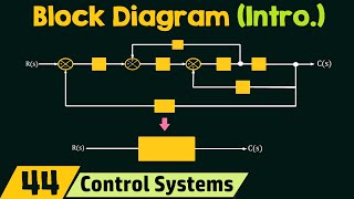
- Block Diagram
A diagram that visually represents the relationships and interactions between different components in a control system.
Reference links
Supplementary resources to enhance your learning experience.