
Common Practical Applications
Interactive Audio Lesson
Listen to a student-teacher conversation explaining the topic in a relatable way.
Digital Lock System
🔒 Unlock Audio Lesson
Sign up and enroll to listen to this audio lesson

Today we're going to look at a practical application of digital circuits: the digital lock. Can anyone tell me what the basic input and output of a digital lock are?

The input is usually a binary code, like a combination of numbers, right?
Exactly! It's a 4-bit code that represents the password. What about the output?

It would be either unlocking or locking the system?
Correct. The outputs represent either unlock (1) or lock (0). Now, can anyone explain the design mechanism behind this?

We compare the entered code with the stored value using something like XOR gates?
Yes! XOR/XNOR gates will help us determine if the entered code matches the stored code. Remember, the output is high only when all bits match. This ensures security!
In summary, the digital lock uses a binary code input for security and uses XOR/XNOR gates to determine access. Does anyone have questions on this?

Just to clarify, why do we use XOR and not just a simple comparison?
Great question! XOR is useful because it gives a true result only when inputs are different. XNOR is best for checking equality when matching. This dual approach enhances security by ensuring that every bit must be correct for access.
Traffic Light Controller
🔒 Unlock Audio Lesson
Sign up and enroll to listen to this audio lesson

Next, let’s shift to our second application: the traffic light controller. Who can tell me the inputs and outputs involved in this system?
I think the input would be timer pulses?
That's correct! The timer pulses trigger transitions. And what are the outputs?
The traffic lights: red, yellow, and green signals?
Exactly right. To design this system, we can use a Moore state machine. Can anyone explain what that means?
A Moore machine changes state based on the input signals, right?
Yes! The current state determines the output, and we can use flip-flops to represent these states. With that, we can control which lights are active. Let’s summarize: this application uses timer inputs to manage light outputs through a state machine. Any further question?
How do the flip-flops actually represent the states?
Good inquiry! Flip-flops hold binary states that correspond to the phases of the traffic light. Each change in state advances the specific light cycle — green, yellow, and red — ensuring smooth traffic flow.
7-Segment Display Driver
🔒 Unlock Audio Lesson
Sign up and enroll to listen to this audio lesson
Now let’s discuss the 7-segment display driver, which transforms binary inputs into visible numbers. What do you think our inputs are?
I believe it takes a 4-bit binary number as input?
Right! And the output?
It activates segments a to g to show the corresponding number?
Correct! To implement this, we create a truth table for the segments. Why do you think we would want to use a ROM lookup table in this context?
Because it can quickly retrieve outputs without calculating every time?
Exactly right! Using a ROM allows for efficient output fetching based on the binary input. In summary, we convert binary inputs to numeric outputs using a truth table or ROM. Does anyone have questions?
Elevator Controller
🔒 Unlock Audio Lesson
Sign up and enroll to listen to this audio lesson
Finally, let’s discuss our last application: the elevator controller. What inputs do you think it deals with?
It probably takes floor requests and sensor inputs?
Exactly! And what outputs could we expect from it?
The motor actions, like moving up or down, and whether the door opens or closes?
Awesome! We rely on priority encoders and counters for ensuring efficiency. How do these components contribute to safe functioning?
They prioritize requests and ensure the elevator doesn’t move until it's safe?
Precisely! They ensure the elevator operates correctly while responding to user requests. Summary for today: The elevator controller takes requests and uses logic to prioritize and control its movements safely. Any remaining queries?
Introduction & Overview
Read summaries of the section's main ideas at different levels of detail.
Quick Overview
Standard
In this section, we explore the common practical applications of digital circuits, such as digital locks, traffic light controllers, 7-segment display drivers, and elevator controllers. Each example demonstrates the inputs, outputs, and design approaches used in these systems.
Detailed
Common Practical Applications in Digital Circuits
In digital circuit design, practical applications serve as excellent examples of how theoretical concepts are implemented in real-world systems. This section explores four major applications, detailing their input and output specifications along with design approaches:
A. Digital Lock (Password-Based System)
- Inputs: Binary keys (e.g., 4-bit code)
- Outputs: Unlock (1) or Lock (0)
- Design Approach: Compare the entered password with a stored binary value using XOR/XNOR gates. The output should be high only when all bits match, ensuring security by correctly identifying legitimate users.
B. Traffic Light Controller (FSM Design)
- Inputs: Timer pulses
- Outputs: Red, Yellow, and Green signals
- Design Approach: Utilize a Moore state machine to define transitions between traffic light states. Flip-flops can represent the current state, with output decoding determining which lights are activated based on the state.
C. 7-Segment Display Driver
- Inputs: 4-bit binary number
- Outputs: Activation of segments (a-g)
- Design Approach: Develop a truth table that outlines which segments correspond to each binary input. The driver may employ combinational logic to determine the state of each segment or implement a ROM lookup table for efficiency.
D. Elevator Controller
- Inputs: Floor requests, sensors
- Outputs: Motor up/down, door open/close
- Design Approach: Implement priority encoders and counters along with finite state machines (FSMs) to ensure the elevator operates safely and efficiently, reflecting user requests in the correct sequence.
Overall, these applications highlight the importance of understanding digital circuits through practical implementations, connecting theoretical knowledge to hands-on engineering.
Youtube Videos


Audio Book
Dive deep into the subject with an immersive audiobook experience.
Digital Lock (Password-Based System)
Chapter 1 of 4
🔒 Unlock Audio Chapter
Sign up and enroll to access the full audio experience
Chapter Content
A. Digital Lock (Password-Based System)
- Inputs: Binary keys (e.g., 4-bit code)
- Output: Unlock (1) or lock (0)
Design Approach:
- Compare entered code with stored value using XOR/XNOR gates.
- Output high only when all bits match.
Detailed Explanation
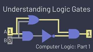
A digital lock functions like a traditional lock but uses binary codes instead of physical keys. The inputs for the lock are binary keys, which can be thought of as a sequence of zeros and ones (for example, a 4-bit code can range from 0000 to 1111). When a user enters a code, the digital system checks it against a pre-stored value. The method uses logic gates like XOR (exclusive OR) or XNOR (exclusive NOR) to compare each entered bit with its corresponding bit in the stored code. The lock opens (output is high or 1) only when all bits are correct; otherwise, it remains locked (output is low or 0).
Examples & Analogies
Think of this digital lock as a combination lock on a safe. Just like you have to enter the exact correct combination to unlock the safe, the digital lock needs the exact binary code to unlock. If even one digit is wrong, the lock doesn't open, similar to how a safe would remain locked if you enter a wrong digit.
Traffic Light Controller (FSM Design)
Chapter 2 of 4
🔒 Unlock Audio Chapter
Sign up and enroll to access the full audio experience
Chapter Content
B. Traffic Light Controller (FSM Design)
- Inputs: Timer pulses
- Outputs: Red, Yellow, Green signals
Design:
- Use a Moore state machine to define signal transitions.
- Use flip-flops to represent states, decode state to output lights.
Detailed Explanation
The traffic light controller is an example of a finite state machine (FSM). In this case, the inputs are timer pulses, which help the controller determine when to change the lights. The FSM operates in defined states: for example, it can be in a red light state, a yellow light state, or a green light state. To keep track of these states, the design uses flip-flops, a type of memory circuit that retains its state until triggered by a clock pulse. The output signals—the actual lights—are activated based on the current state of the machine.
Examples & Analogies
Consider a traffic cop directing traffic. When the cop raises a specific hand signal, it indicates which direction should stop or go, similar to how the red, yellow, and green lights communicate to drivers. The cop has a specific order of signals, just as the traffic light controller has defined states for each light that change at timed intervals.
7-Segment Display Driver
Chapter 3 of 4
🔒 Unlock Audio Chapter
Sign up and enroll to access the full audio experience
Chapter Content
C. 7-Segment Display Driver
- Inputs: 4-bit binary number
- Output: Activates 7 segments (a–g)
Design:
- Build a truth table for each segment.
- Use combinational logic or ROM lookup table.
Detailed Explanation
A 7-segment display is a common electronic display device that can show numbers by illuminating different segments labeled from a to g. The input is a 4-bit binary number, which can represent values from 0 to 15 in decimal. To determine which segments light up for each possible input, designers create a truth table, which explicitly maps input combinations to output segments. The design can utilize combinational logic (like AND, OR gates) to light the appropriate segments, or a ROM lookup table that stores the configuration for each input.
Examples & Analogies
Imagine reading a digital clock. The numbers are displayed using segments made of lights, where only specific segments light up to form the numbers 0-9. Similarly, a 7-segment display uses its segments for forming numbers, just like the display on your microwave does—each digit shines a unique combination of segments.
Elevator Controller
Chapter 4 of 4
🔒 Unlock Audio Chapter
Sign up and enroll to access the full audio experience
Chapter Content
D. Elevator Controller
- Inputs: Floor requests, sensors
- Outputs: Motor up/down, door open/close
Design:
- Use priority encoders, counters, and FSMs.
- Logic must ensure safe and correct sequencing.
Detailed Explanation
An elevator controller manages the elevator's operation by responding to floor requests from users. The inputs include requests (button presses) from various floors and sensor data indicating the elevator's current position. The design typically employs priority encoders to determine which request to service first, ensuring that the elevator operates efficiently. Counters and FSMs keep track of the elevator's state—whether it is moving up or down, or if the doors are opening or closing. The system's logic must ensure safe operation to prevent accidents.
Examples & Analogies
Think of the elevator controller as a bus driver addressing which stops to make. Just as the driver checks the requests of passengers for different stops, the elevator controller assesses which floor a passenger wants to go. Safety is key in both situations: the bus driver must ensure passengers board and disembark safely, just as the elevator controller must ensure doors don’t close on passengers or that the elevator doesn’t move when it shouldn’t.
Key Concepts
-
Digital Lock: A system requiring a binary code for access.
-
Traffic Light Controller: Manages light transitions based on timers.
-
7-Segment Display: Shows numerical values using a specific arrangement of segments.
-
Elevator Controller: Automates elevator floor selection and door operations.
-
Moore State Machine: A model for designing state-driven outputs.
Examples & Applications
A digital lock typically utilizes a 4-bit binary password that must be entered correctly to unlock.
A traffic light system might rely on a timer that cycles through red to green lights every 60 seconds.
Memory Aids
Interactive tools to help you remember key concepts
Rhymes
For locks that secure with a code, use XOR to check the road.
Stories
Imagine an elevator that only opens for the right button pressed amid a flurry of requests, prioritizing safety as it goes.
Memory Tools
Think of 'LITE' (Lock, Input, Timer, Elevate) for remembering designs related to locking systems.
Acronyms
DTS (Digital Lock, Traffic Light, Segment Display) helps remind you of these applications.
Flash Cards
Glossary
- Digital Lock
A security device that requires a specific binary code to unlock.
- Traffic Light Controller
A system that manages the sequence of traffic lights at intersections.
- 7Segment Display Driver
A digital circuit that converts binary input into visual numbers through segments.
- Elevator Controller
An automated system managing the operations of an elevator based on user requests.
- Moore State Machine
A finite state machine whose outputs depend only on the current state.
Reference links
Supplementary resources to enhance your learning experience.