
Modern Tools for Digital Circuit Design
Interactive Audio Lesson
Listen to a student-teacher conversation explaining the topic in a relatable way.
Logic Simulators
🔒 Unlock Audio Lesson
Sign up and enroll to listen to this audio lesson

Today, we're discussing logic simulators, which are vital for designing and testing our circuits visually. Can anyone tell me how they think this could benefit circuit design?

I guess it would help see if the circuit works before building it.
Exactly! By using a drag-and-drop interface, designers can quickly test different configurations without needing physical components. This saves time and reduces errors. Can anyone think of why reducing errors might be important?

Less errors mean we won't waste resources and can focus on getting the design right.
Spot on! Now remember a key term, 'simulate before you build'. This idea underpins modern circuit design.
Circuit Design Software
🔒 Unlock Audio Lesson
Sign up and enroll to listen to this audio lesson

Moving on to circuit design software, like Multisim. How do you think such software helps in building circuits?

It probably has a lot of components in it, right?
Right! It allows designers to incorporate various components all in one place. It also helps simulate the IC-level design. Why do you think that might be important?

It means we can test how different components work together more easily.
Exactly! That's crucial for avoiding compatibility issues and ensuring our circuits function correctly as a system.
HDL-Based Design Tools
🔒 Unlock Audio Lesson
Sign up and enroll to listen to this audio lesson
Now let's delve into HDL-based design tools like VHDL and Verilog. What do you think sets these tools apart from traditional circuit design methods?
I think they let us write code for circuits, which might be easier than wiring everything up!
Great insight! By using code, engineers can define complex behaviors and ensure accuracy prior to physical implementation. Remember, 'Code it to control it'.
Can we simulate those designs too?
Absolutely, simulation allows for testing behaviors without risking hardware failure!
Microcontroller Simulation
🔒 Unlock Audio Lesson
Sign up and enroll to listen to this audio lesson
Finally, let's look at microcontroller simulation, like using Arduino. How do you think this fits into our circuit design process?
It probably helps to make sure our designs work with real-world components.
Exactly! It allows for prototyping and testing circuits in a practical setting without extensive resources. Who remembers our phrase, 'Test and iterate'?
I do! It helps us refine our designs until they're perfect.
Fantastic! Keep this in mind as we work on more real-world applications.
Importance of Modern Tools
🔒 Unlock Audio Lesson
Sign up and enroll to listen to this audio lesson
Let's summarize. Why is it crucial to use modern tools in digital circuit design?
They help save time and reduce errors!
And they allow for complex designs to be modeled accurately!
Exactly! Remember, effective tools bridge the gap between theory and practical application, reinforcing the importance of learning these technologies.
Introduction & Overview
Read summaries of the section's main ideas at different levels of detail.
Quick Overview
Standard
Digital circuit design relies on various modern tools that enhance efficiency and accuracy. This section discusses different tools such as logic simulators, circuit design software, HDL-based design tools, and their use in simulation with microcontrollers, highlighting their significance in contemporary design processes.
Detailed
Modern Tools for Digital Circuit Design
Digital circuit design has evolved significantly, leveraging various modern tools that streamline the design process and improve operational accuracy. Key tools include:
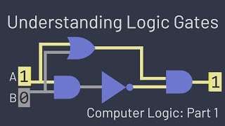
- Logic Simulators: Designed for drag-and-drop logic simulation, these tools allow engineers to visualize and test logic circuits before physical implementation.
- Circuit Design Software: Programs like Multisim enable circuit design at the IC level, facilitating complex design processes that integrate various components and technology.
- HDL-Based Design Tools: Hardware Description Languages (HDLs) such as VHDL and Verilog are crucial for designing and simulating field-programmable gate arrays (FPGAs), allowing engineers to program specific functionalities and test designs in a virtual environment.
- Microcontroller Simulation: Tools like Arduino simplify the testing process by enabling simulation of microcontroller interactions with digital circuits, allowing for quick prototyping and troubleshooting.
The use of these tools greatly enhances the efficiency, accuracy, and reliability of digital circuit design, bridging theoretical concepts with practical outcomes.
Youtube Videos


Audio Book
Dive deep into the subject with an immersive audiobook experience.
Logic Simulation Tools
Chapter 1 of 5
🔒 Unlock Audio Chapter
Sign up and enroll to access the full audio experience
Chapter Content
To Purpose
Lo Drag-and-drop logic simulation
Detailed Explanation
Logic simulation tools are software platforms that allow users to create and test digital circuits visually. Users can drag and drop components like gates into a workspace, connecting them to form circuits without needing to physically wire anything. This simulation allows designers to see how their circuit would work and identify issues before actual hardware implementation. By simulating the circuit, users can verify its logic and functionality using various input conditions.
Examples & Analogies
Imagine using a digital drawing app to design a floor plan for your house. You can move walls and furniture around to see how everything fits before you start the actual building process. Similarly, logic simulation tools let you create digital circuits on a computer screen, allowing for adjustments and corrections before creating the real circuit.
Circuit Design with IC-Level Parts
Chapter 2 of 5
🔒 Unlock Audio Chapter
Sign up and enroll to access the full audio experience
Chapter Content
Mul Circuit design with IC-level parts
Detailed Explanation
When designing circuits at the integrated circuit (IC) level, designers focus on using existing ICs which contain multiple logic gates within a single chip. This method allows for compact and efficient design, as a designer can utilize proven components that are widely available. It simplifies the process of building larger circuits by providing a standard way to integrate complex functions without starting from scratch.
Examples & Analogies
Think of it like using pre-made furniture pieces to build a room instead of crafting everything from raw materials. Just as buying pre-fabricated furniture saves time and ensures quality, using IC-level parts in circuit design helps engineers quickly create reliable circuits.
HDL-Based FPGA Design
Chapter 3 of 5
🔒 Unlock Audio Chapter
Sign up and enroll to access the full audio experience
Chapter Content
Qu HDL-based FPGA design (VHDL/Verilog)
Detailed Explanation
Hardware Description Languages (HDLs) such as VHDL and Verilog are used to describe the operation of electronic circuits at a high level. When implementing designs on Field Programmable Gate Arrays (FPGAs), designers write code in these languages, which the FPGA can then interpret to create the desired digital function. This method allows for rapid prototyping and refactoring of designs, making it easier to test and deploy complex circuits.
Examples & Analogies
Think of HDLs like a recipe book for a chef. Just as a chef follows a recipe to create a dish, engineers write HDL code that specifies how the circuit should behave. This 'recipe' is then translated by the FPGA to bring the digital circuit to life.
Simulation with Microcontrollers
Chapter 4 of 5
🔒 Unlock Audio Chapter
Sign up and enroll to access the full audio experience
Chapter Content
Pr Simulation with microcontrollers
Detailed Explanation
Simulating designs with microcontrollers involves testing the interaction between the microcontroller and the digital circuit. By simulating the behavior of both software and hardware together, engineers can identify integration issues early on. This process often involves using simulation software that mimics the microcontroller's operation, allowing for an in-depth analysis of how the program and the circuit interact.
Examples & Analogies
Consider this process like rehearsing a play where actors (microcontrollers) practice their lines and cues with the set (the circuit). This rehearsal allows everyone to ensure the timing and interactions are perfect before the actual performance, much like testing the circuit with simulated microcontrollers ensures proper functionality.
Arduino for Basic Digital Simulation
Chapter 5 of 5
🔒 Unlock Audio Chapter
Sign up and enroll to access the full audio experience
Chapter Content
Tin Arduino + basic digital simulation
Detailed Explanation
Arduino platforms are popular tools for beginners and professionals to prototype and test simple digital circuits. An Arduino can simulate sensor interactions and control outputs based on programmed logic. This allows designers to create physical prototypes that can be manipulated and tested in real-time, providing immediate feedback and opportunities for learning.
Examples & Analogies
Using an Arduino for circuit design is like experimenting with simple ingredients in cooking. Beginners can use a few basic components to create various recipes (or circuits) and see what works, leading to a deeper understanding of how different elements come together, much like how cooking helps you learn flavors and techniques.
Key Concepts
-
Logic Simulators: Tools for visualizing and testing circuit designs.
-
Circuit Design Software: Programs used for efficiently creating and simulating electronic circuits.
-
HDL-Based Design: Languages like VHDL that allow for defining circuit behaviors through code.
-
Microcontroller Simulation: Practical prototyping tools that help test circuit interactions.
Examples & Applications
Using a logic simulator, students design a simple AND gate and observe its behavior before building it physically.
Designing a circuit to control LEDs with Multisim, simulating different scenarios to ensure the design meets specifications.
Memory Aids
Interactive tools to help you remember key concepts
Rhymes
For circuits that glow, use the tools to know, simulate and build to help them flow.
Stories
Imagine a group of students building a racecar. They draw their designs on paper but fail the trial runs. They switch to tools like simulators and software, leading to perfect designs and victories in the race.
Memory Tools
Remember: 'Simulators Simulate, Design Software Defines, HDL Codes, Arduino Tests'. Summarized as 'S-D-H-A' for circuit design tools.
Acronyms
Think 'SMAH'
Simulation Tools
Multisim
Arduino
HDL - all essential for digital circuit design.
Flash Cards
Glossary
- Logic Simulators
Software tools that provide visual representations of how logic circuits function, allowing for simulation and testing.
- Circuit Design Software
Applications that facilitate the design and simulation of electronic circuits, often including various components.
- HDL (Hardware Description Language)
A specialized language used to describe the structure and behavior of electronic circuits.
- FPGA (Field Programmable Gate Array)
A type of digital circuit that can be configured to perform specific functions during operation.
- Microcontroller
A compact integrated circuit designed to govern a specific operation in an embedded system.
Reference links
Supplementary resources to enhance your learning experience.