
Apply State Machines in Digital Circuit Design
Interactive Audio Lesson
Listen to a student-teacher conversation explaining the topic in a relatable way.
Introduction to FSMs
🔒 Unlock Audio Lesson
Sign up and enroll to listen to this audio lesson

Welcome class! Today, we're going to dive into Finite State Machines, or FSMs, which are crucial in digital circuit design. Can anyone tell me what they think a state machine is?

Is it something that helps control how a system reacts to different inputs?
Exactly, Student_1! An FSM describes how a system behaves based on inputs and past events. It has three main components: states, transitions, and outputs. Remember the acronym STO for States, Transitions, and Outputs.

So, states are like different modes the machine can be in, right?
That's right! For example, in a traffic light system, states could be red, yellow, and green. Let's move on to transitions—can anyone explain what they are?
Types of State Machines
🔒 Unlock Audio Lesson
Sign up and enroll to listen to this audio lesson

Now let's discuss the two types of FSMs: Moore and Mealy machines. Student_3, do you want to take a guess at the main difference?

I think Moore machines only depend on the current state for output, while Mealy machines depend on state and input?
Correct! Moore machines have outputs that are solely tied to their states while Mealy machines can change output based on input. Remember this with the mnemonic M for Moore and Modes only!

What would be an example of a situation where we might use a Mealy machine instead of a Moore machine?
Great question, Student_4! A serial data receiver is a perfect example where immediate responsiveness to input data is needed.
Components of an FSM
🔒 Unlock Audio Lesson
Sign up and enroll to listen to this audio lesson
Let’s break down the components of an FSM. We have six key components. Can anyone name one?
States?
Yes! States indicate the current mode of operation, like IDLE or LOAD. Next, what's another component?
The input signals?
Correct! Inputs can be buttons or sensors. Don't forget about the memory bit! We use flip-flops to store the current state. This gives us the acronym SINE for States, Inputs, Next-State Logic, and Outputs.
Design Flow of FSMs
🔒 Unlock Audio Lesson
Sign up and enroll to listen to this audio lesson
After we understand FSMs, we need to design one. The design flow includes key steps. Who can list a step?
Problem definition?
Yes! It’s vital to define what behavior the system should exhibit. Another step would be creating a state diagram, any guesses on what that looks like?
Is it like a diagram showing states and transitions with arrows connecting them?
Exactly! Visuals help us understand how states interact. A helpful mnemonic here is PD-SDL for Problem Definition and State Diagram Line.
Applications of FSMs
🔒 Unlock Audio Lesson
Sign up and enroll to listen to this audio lesson
Lastly, let's talk about real-world applications of FSMs. Student_1, can you think of any example where FSMs are used?
A vending machine could be one?
Excellent! Vending machines use FSMs to manage the input of coins and dispense products accordingly. Another example is elevator control, where the FSM uses requests to move between floors.
What about in robotics? Do they use FSMs too?
Absolutely! Robotics often uses FSMs for decision-making based on sensor inputs. Remember the acronym RAM for Robotics, Applications, and Machines.
Introduction & Overview
Read summaries of the section's main ideas at different levels of detail.
Quick Overview
Standard
Finite state machines (FSMs) are a foundational concept in digital circuit design. This section outlines what FSMs are, the types including Moore and Mealy, their components, design flow, encoding methods, hardware implementation, and real-world applications.
Detailed
Apply State Machines in Digital Circuit Design
In digital design, Finite State Machines (FSMs) are essential models that help describe the behavior of electronic systems through states, transitions, and outputs. An FSM comprises distinct states, transitions triggered by inputs, and outputs that depend on the current state. There are two main types of FSMs: Moore machines, where outputs depend solely on states, and Mealy machines, which are influenced by both states and current inputs.
Key Components of FSMs
- States: Unique modes like IDLE, LOAD, DONE.
- Inputs: External signals (e.g., buttons, sensors).
- Next-State Logic: Logic that determines state transitions.
- Output Logic: Drives outputs based on the current state.
- Memory (Flip-Flops): Used to store the current state.
- Clock: Synchronizes transitions between states.
Design Flow of FSMs
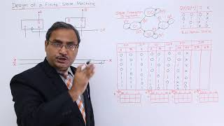
The FSM design flow consists of critical steps: problem definition, creating a state diagram, forming a state table, binary state assignment, deriving flip-flop input equations, designing output logic, and then implementing the circuit through simulation or hardware.
Real-World Applications
FSMs are utilized in various applications, like vending machines that track coins, elevator control systems that move between floors, and password locks that match input sequences against stored codes.
Understanding these concepts in detail supports effective design and modularity in digital systems.
Youtube Videos


Audio Book
Dive deep into the subject with an immersive audiobook experience.
What is a State Machine?
Chapter 1 of 5
🔒 Unlock Audio Chapter
Sign up and enroll to access the full audio experience
Chapter Content
A State Machine (or Finite State Machine, FSM) is a digital logic model used to describe the behavior of systems that change based on inputs and past events. An FSM consists of:
● States: Distinct modes of operation
● Transitions: Movement between states based on input
● Outputs: Depend on current state (and sometimes input)
Detailed Explanation
A State Machine, represented as an FSM, is a model that helps in understanding how systems behave under various situations. The state machine is made up of several components: states represent different conditions or phases the system can be in; transitions indicate how the system moves from one state to another based on inputs; and outputs give the resultant actions of the system depending on the current state, and occasionally influenced by the current inputs.
Examples & Analogies
Think of a traffic light system as a state machine. Each light—red, yellow, and green—represents a different state. The changes between these states (like transitioning from red to green) happen based on certain inputs, like the timer or sensors that detect cars waiting at a stop.
Types of State Machines
Chapter 2 of 5
🔒 Unlock Audio Chapter
Sign up and enroll to access the full audio experience
Chapter Content
| FS | Output Depends | Example Use Case |
|---|---|---|
| M | Current state only | Traffic light controller |
| o | Current state + current input | Serial data receiver, counters |
Detailed Explanation
State machines can be categorized based on how their outputs are determined. The Moore type’s outputs depend solely on the current state. For example, in a traffic light controller, the output (the light that is on) is determined by the light's current state alone. On the other hand, the Mealy type's outputs depend on both the current state and the input. This means that a state can adjust its output based on immediate external conditions, like in a serial data receiver where the output can change based on the input it is processing.
Examples & Analogies
Consider a vending machine. It may embody a Moore FSM because the output (the product dispensed) depends only on the state it is currently in (e.g., ‘accepting coins’ or ‘dispensing product’), while a bank ATM could be a Mealy machine, where the output can also depend on inputs like user selection.
Components of a State Machine
Chapter 3 of 5
🔒 Unlock Audio Chapter
Sign up and enroll to access the full audio experience
Chapter Content
- States – Defined modes like IDLE, LOAD, DONE
- Inputs – External signals (buttons, sensors, etc.)
- Next-State Logic – Determines how to transition
- Output Logic – Drives outputs based on state
- Memory (Flip-Flops) – Store the current state
- Clock – Synchronizes state transitions
Detailed Explanation
A state machine is constructed using several key components. States are the various conditions the system can exist in, such as 'IDLE' or 'LOAD'. Inputs are the signals that trigger changes in the state, like the press of a button. Next-state logic defines the rules for how the transition occurs from one state to another based on current state and inputs. Output logic takes the current state and produces the appropriate outputs. Memory is maintained, often using flip-flops, to remember the current state. Finally, a clock signal is crucial for synchronizing these transitions, ensuring they happen at predictable intervals.
Examples & Analogies
Imagine a video game console. The states are different stages of a game like 'Main Menu', 'Playing', or 'Pause'. Inputs are the buttons you press on the controller. The next-state logic decides what happens when you press a button, like moving from 'Main Menu' to 'Playing'. The output is what you see on screen. Flip-flops keep track of the stage you're in, and the clock makes sure the game processes inputs in real-time.
FSM Design Flow
Chapter 4 of 5
🔒 Unlock Audio Chapter
Sign up and enroll to access the full audio experience
Chapter Content
- Problem Definition
Describe required behavior and system states. - State Diagram
Draw states and transitions (circles and arrows). - State Table
List all present states, inputs, next states, and outputs. - Binary State Assignment
Assign binary codes to each state. - Flip-Flop Input Equations
Use K-maps to derive expressions. - Output Logic Design
Use combinational logic or HDL. - Circuit Implementation or Simulation
Detailed Explanation
To design an FSM, one needs to follow structured steps. First, you define the problem clearly, outlining how you expect the system to behave and identifying its states. Next, you draw a state diagram that visually maps the states and the transitions between them with arrows. A state table is then created to detail all present states alongside their inputs and the resulting next states and outputs. States are then assigned binary values, which facilitates their use in digital circuits. Further, flip-flop input equations that dictate transitions are derived using Karnaugh maps. After designing the logic for outputs, the next step is to either implement this design in a physical circuit or simulate it digitally.
Examples & Analogies
Think of designing an app. You start with requirement gathering (defining the problem), followed by sketching out the user interface (state diagram), and then documenting user interactions (state table). Next, you assign functions (binary state assignment) and write the logic for what happens when buttons are clicked (flip-flop equations). Finally, you code it (output logic) and test it out (circuit implementation). Each step builds on the previous one to create a functional product.
Example: Simple Traffic Light Controller (Moore FSM)
Chapter 5 of 5
🔒 Unlock Audio Chapter
Sign up and enroll to access the full audio experience
Chapter Content
States:
● S0: Red
● S1: Red + Yellow
● S2: Green
● S3: Yellow
Transitions:
Each state lasts for a fixed number of clock cycles.
State Table (Simplified):
Prese Ne Outp
nt xt uts
State Sta
te
S0 S1 Red
S1 S2 Red + Yellow
S2 S3 Green
S3 S0 Yellow
Detailed Explanation
A traffic light controller can be modeled as a Moore FSM with four states: S0 (Red), S1 (Red + Yellow), S2 (Green), and S3 (Yellow). The transitions between these states occur after a predetermined number of clock cycles, ensuring a smooth change of lights. The simplified state table illustrates these transitions and their associated outputs, such as what color light is displayed for each state.
Examples & Analogies
Imagine you are at a traffic light. The light stays red for a certain duration (S0), followed by a brief moment of red + yellow (S1) to prepare drivers for the next state, green (S2), which allows cars to go. After some time, it turns yellow (S3) before going back to red. Each of these states has a specific duration, making it predictable and safe for drivers on the road.
Key Concepts
-
FSM: A model to describe state behaviors.
-
Types: Moore and Mealy machines differ in output dependency.
-
Components: States, inputs, next-state logic, output logic, and memory.
-
Design Flow: Steps involved in creating an FSM.
Examples & Applications
Traffic light controllers utilize FSMs to switch between red, yellow, and green states based on timing and transitions.
A serial data receiver uses a Mealy machine to react immediately to input signals for processing.
Memory Aids
Interactive tools to help you remember key concepts
Rhymes
Transitions happen with care, from state to state, they will share.
Stories
Imagine a traffic light as a state machine, it knows when to change and in what routine.
Memory Tools
Use SINE for remembering States, Inputs, Next-state logic, and Outputs.
Acronyms
M for Moore outputs only depend on Moments, while Mealy responds to Moments and Movements!
Flash Cards
Glossary
- State Machine (FSM)
A digital model that describes the behavior of a system based on states, transitions, and outputs.
- Moore Machine
A type of FSM where outputs depend solely on the current state.
- Mealy Machine
A type of FSM where outputs depend on both the current state and inputs.
- Transitions
The movement between states based on input.
- States
Distinct modes of operation within a state machine.
Reference links
Supplementary resources to enhance your learning experience.