
FSM Design Flow
Interactive Audio Lesson
Listen to a student-teacher conversation explaining the topic in a relatable way.
Problem Definition
🔒 Unlock Audio Lesson
Sign up and enroll to listen to this audio lesson

To start our FSM Design Flow, we must first define the problem. What do you think problem definition entails?

It’s about understanding what the FSM should do, right?
Exactly! We need to describe the required behavior and enumerate the system states. Can anyone tell me why this step is so crucial?

Without clear definitions, we might end up with a design that doesn’t meet our needs!
Correct! This establishes the foundation for our entire FSM. So remember: Before starting to design, always define the problem. Let's move on to the next step.
State Diagram
🔒 Unlock Audio Lesson
Sign up and enroll to listen to this audio lesson

Next in the FSM Design Flow is creating a State Diagram. This visual tool helps us visualize states and transitions. Can anyone explain what we include in a state diagram?

Circles for the states and arrows for the transitions, right?
Exactly! Circles represent distinct states, while arrows show how to move between them. Why do you think using a diagram is beneficial?

It helps simplify complex state behavior!
Absolutely! A clear diagram assists everyone in understanding the FSM design. This visual aid remains a reference throughout our design process.
State Table
🔒 Unlock Audio Lesson
Sign up and enroll to listen to this audio lesson
Next, we have the State Table. It's a key component in our design. Who can explain what a State Table contains?
It lists all the present states, inputs, next states, and outputs.
Correct! The State Table serves as a reference and an essential tool for anticipating system behavior. How does it link back to defining our FSM?
It helps ensure our design meets the behavioral requirements we defined earlier.
Exactly! The State Table connects our problem definition to the design, making it an important element in the designated flow.
Binary State Assignment
🔒 Unlock Audio Lesson
Sign up and enroll to listen to this audio lesson
Let’s discuss Binary State Assignment. This is where we assign binary codes to each state. Why is that important?
It creates unique identifiers for each state in a digital design.
Right! Furthermore, assigning binary values simplifies the implementation in digital circuits. Needed for memory reference—who can summarize how this integrates with earlier steps?
It uses the information from our State Diagram and Table to make sure the design logic is clear!
Well done! A strong understanding of this step enhances our FSM design process.
Circuit Implementation
🔒 Unlock Audio Lesson
Sign up and enroll to listen to this audio lesson
Finally, we arrive at Circuit Implementation or Simulation. Why might this step be the most vital?
It’s the point where our design becomes a working system.
Exactly! This is where we validate our FSM in real-world scenarios. Additionally, what can you do if you find issues during this step?
Go back to previous steps and adjust the design until it works!
Absolutely! The design flow is iterative. Every stage is essential for crafting a functional FSM. Remember, practice makes perfect. Any last thoughts on the FSM Design Flow?
Introduction & Overview
Read summaries of the section's main ideas at different levels of detail.
Quick Overview
Standard
This section details the seven fundamental steps of the FSM Design Flow, including problem definition, drawing state diagrams, state tables, binary state assignment, and implementing logic equations, culminating in circuit implementation or simulation.
Detailed
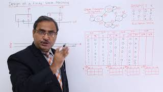
FSM Design Flow
The FSM Design Flow consists of a series of structured steps that facilitate the successful creation of a finite state machine. These steps provide a roadmap for designing robust digital systems. The critical stages include:
- Problem Definition: Clearly describe the behavior required from the system, ensuring you outline all necessary states.
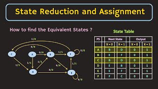
- State Diagram: Visual representation of states and transitions using circles (for states) and arrows (for transitions) to depict how the FSM operates.
- State Table: A comprehensive table that includes all present states, inputs, and their corresponding next states and outputs, serving as a reference during implementation.
- Binary State Assignment: Assign binary codes to each state, a crucial step for creating distinct identifiers for the states within digital logic.
- Flip-Flop Input Equations: Derive logical equations for the flip-flop inputs using Karnaugh maps (K-maps), which simplifies the design process.
- Output Logic Design: Determine the output logic either through combinational logic circuits or hardware description languages (HDLs).
- Circuit Implementation or Simulation: Finally, implement the designed circuit either through physical components or via simulation software to validate the design.
Understanding this FSM Design Flow is essential for effectively executing decisions in digital circuit design.
Youtube Videos


Audio Book
Dive deep into the subject with an immersive audiobook experience.
Problem Definition
Chapter 1 of 7
🔒 Unlock Audio Chapter
Sign up and enroll to access the full audio experience
Chapter Content
- Problem Definition
Describe required behavior and system states.
Detailed Explanation
The first step in the FSM design flow is to clearly define the problem we want to solve with the FSM. This involves detailing the expected behavior of the system and identifying all possible states it can be in. Essentially, we must answer questions like: What inputs will the system respond to? What outcomes do we want from these inputs? A precise problem definition sets the groundwork for the subsequent steps in the design.
Examples & Analogies
Imagine you want to design a simple washing machine. The problem definition might include stating that it will have states like 'washing', 'spinning', and 'rinsing', and it will respond to inputs such as 'start', 'pause', and 'stop'. This clear outline helps guide the rest of the design.
State Diagram
Chapter 2 of 7
🔒 Unlock Audio Chapter
Sign up and enroll to access the full audio experience
Chapter Content
- State Diagram
Draw states and transitions (circles and arrows).
Detailed Explanation
After defining the problem, the next step is to create a state diagram. This visual representation maps out all the states identified in the previous step, showing how the system transitions from one state to another based on input. Typically, circles represent states, and arrows represent transitions. This diagram helps ensure that the designer has a comprehensive understanding of the system's flow and is essential for creating an accurate state table.
Examples & Analogies
Think of a flowchart for planning a recipe. Each step in the recipe can be seen as a state, and the arrows between them depict what you do next based on what ingredients you have. Similar to that chart, a state diagram provides a roadmap for how different states of the FSM interact.
State Table
Chapter 3 of 7
🔒 Unlock Audio Chapter
Sign up and enroll to access the full audio experience
Chapter Content
- State Table
List all present states, inputs, next states, and outputs.
Detailed Explanation
The state table is a structured way to summarize the information depicted in the state diagram. It lists current states, possible inputs, corresponding next states, and outputs for each state. This table is crucial for the designer because it provides a clear and concise reference to understand how every input affects the system and what outputs are generated based on the current state.
Examples & Analogies
Imagine you're programming a video game character. The state table could display the character's current status ('running', 'jumping'), what actions can be taken (inputs), what the next state will be (like 'sliding'), and what the character does in each state (output, such as gaining points). It organizes the logic behind the game's behavior.
Binary State Assignment
Chapter 4 of 7
🔒 Unlock Audio Chapter
Sign up and enroll to access the full audio experience
Chapter Content
- Binary State Assignment
Assign binary codes to each state.
Detailed Explanation
In this step, each identified state is assigned a unique binary code. This is critical because digital systems operate using binary data. For example, if there are four states, you may assign them binary codes such as 00, 01, 10, and 11. This encoding is essential for the implementation phase where the states need to be represented in a format that hardware can recognize and process.
Examples & Analogies
Consider how different colors might be represented as codes in a game; for instance, 'red' could be 00, 'green' as 01, and 'blue' as 10. Just like these codes help define the colors, binary coding of states allows the FSM to easily identify and react to different states.
Flip-Flop Input Equations
Chapter 5 of 7
🔒 Unlock Audio Chapter
Sign up and enroll to access the full audio experience
Chapter Content
- Flip-Flop Input Equations
Use K-maps to derive expressions.
Detailed Explanation
Next, we need to define how each flip-flop within the FSM will change state based on the current state and inputs. This is done using Karnaugh maps (K-maps), which provide a systematic way to simplify the logical equations that dictate the state transitions. The output from these K-maps will provide the necessary logic expressions that will be implemented in flip-flops to achieve the desired state transitions.
Examples & Analogies
Think of it like figuring out the easiest way to make a recipe. Instead of writing a long list of instructions, you use K-maps to represent all the ways you can combine ingredients. This shows you the simplest steps to get your dish, much like simplifying equations to make the implementation of an FSM straightforward.
Output Logic Design
Chapter 6 of 7
🔒 Unlock Audio Chapter
Sign up and enroll to access the full audio experience
Chapter Content
- Output Logic Design
Use combinational logic or HDL.
Detailed Explanation
The output logic design defines how the outputs of the state machine will be generated based on its current state and inputs. This can be implemented either using combinational logic (such as AND, OR, NOT gates) or through Hardware Description Language (HDL) like VHDL or Verilog. This design is critical to ensure that the system behaves as expected under all possible input scenarios.
Examples & Analogies
Imagine programming a thermostat. Based on the current temperature (state) and a setpoint (input), it must decide whether to turn the heater on or off (output). The rules that determine this can be implemented using logic gates or written in a programming language, just as in our FSM design.
Circuit Implementation or Simulation
Chapter 7 of 7
🔒 Unlock Audio Chapter
Sign up and enroll to access the full audio experience
Chapter Content
- Circuit Implementation or Simulation
Detailed Explanation
The final step is to either implement the FSM in a physical circuit or simulate it using software tools. This allows us to verify that the designed FSM behaves correctly under various input conditions. Hardware implementation involves building the circuit with components like flip-flops and logic gates, while simulation uses software to test the behavior without physical components.
Examples & Analogies
This step is similar to creating a prototype for a new gadget. Before manufacturing it, designers will either build a model to test its functionality or use computer software to simulate how it will work in real life. This ensures any flaws are identified and corrected before final production.
Key Concepts
-
Problem Definition: Clarity of behavior requirements is critical for successful FSM design.
-
State Diagram: Visual tools aiding in understanding and illustrating FSM behavior.
-
State Table: Essential for outlining current states, inputs, outputs, and transitions.
-
Binary State Assignment: A crucial step for implementing unique identifiers for states.
-
Flip-Flop Input Equations: Deriving necessary inputs for sequential circuit design.
-
Output Logic Design: Developing the logic necessary to achieve desired outputs.
-
Circuit Implementation: The final phase to validate the designed FSM.
Examples & Applications
In designing a traffic light controller, the Problem Definition might state it should transition through red, yellow, and green states based on a timer.
Creating a State Diagram for a simple vending machine shows states such as IDLE, COIN_INSERTED, and ITEM_DISPENSED, with arrows representing transitions like inserting a coin.
Memory Aids
Interactive tools to help you remember key concepts
Rhymes
Define the problem, draw a diagram, create a table, assign the code, then design the output, circuit, and simulation road.
Stories
Imagine you're a traffic controller. First, you write down the rules (Problem Definition), then you sketch how the lights should change (State Diagram), list rules for each light (State Table), mark their colors (Binary State Assignment), and work out how the sensors trigger each color (Output Logic), finally checking it all works in a simulation.
Memory Tools
PDSB FOC - Problem Definition, State Diagram, State Table, Binary state Assignment, Flip-Flop equations, Output Logic, Circuit Implementation.
Acronyms
Use PDSBFOC for remembering FSM Design Flow steps.
Flash Cards
Glossary
- FSM (Finite State Machine)
A computational model used to design digital logic systems that can be in one of many states at any time, capable of transitioning between states based on inputs.
- State Diagram
A graphical representation of states and transitions in a state machine, illustrating how a system behaves in response to inputs.
- State Table
A structured table that outlines all current states, possible inputs, resultant next states, and corresponding outputs.
- Binary State Assignment
The process of assigning unique binary identifiers to each state of an FSM to facilitate its implementation in digital circuits.
- FlipFlop Input Equations
Logical expressions derived to determine the inputs necessary for flip-flops in an FSM based on the current state and inputs.
- Output Logic Design
The stage involving the creation of logical circuits or HDL code to govern the outputs of a state machine.
- Circuit Implementation
The final phase where the designed FSM is constructed physically or simulated in software to verify functionality.
Reference links
Supplementary resources to enhance your learning experience.