
HDL Example (VHDL FSM Snippet)
Interactive Audio Lesson
Listen to a student-teacher conversation explaining the topic in a relatable way.
Introduction to FSM in HDL
🔒 Unlock Audio Lesson
Sign up and enroll to listen to this audio lesson

Today we're going to explore a practical example of a finite state machine using VHDL. Can anyone remind me what an FSM is and its components?

It's a model that represents the different states of a system!

And it includes states, transitions, and outputs depending on those states!
Exactly! The FSM reacts to inputs and transitions between states, and today we'll see how we can capture that behavior in VHDL. Remember, the VHDL process is key to describing how FSMs operate.
Understanding the VHDL Snippet Structure
🔒 Unlock Audio Lesson
Sign up and enroll to listen to this audio lesson

Now let's take a look at the VHDL code snippet. The process begins with the statement 'process(clk, reset)'. Can anyone tell me what that means?

It means that this process will be sensitive to changes in the clock and reset signals.
Correct! The process executes when there's a change in either of those signals. When the reset signal is high, what happens to our FSM?

The FSM goes back to its initial state S0!
Right! And when the clock rises, we look at the current state and move to the next one using a case statement. Let’s ensure we understand how to read that next.
State Transitions in VHDL
🔒 Unlock Audio Lesson
Sign up and enroll to listen to this audio lesson
In our case statement, we define the state transitions. If we are in S0, what happens next?
We transition to S1!
Correct! Can anyone summarize what happens when we reach each state?
From S0 to S1, then to S2, then S3, and finally back to S0. It’s a loop!
Great recall! These transitions form the core behavior of our FSM. By using HDL, we allow for a clear representation of how the system behaves over time.
Importance of Learning VHDL for FSMs
🔒 Unlock Audio Lesson
Sign up and enroll to listen to this audio lesson
Why do you think it's important for us to learn VHDL with respect to FSMs specifically?
Because many digital circuits require precise control of state transitions, and VHDL helps us define that clearly.
It makes troubleshooting easier since the code clearly shows how inputs lead to outputs!
Exactly! VHDL not only provides clarity but also allows us to implement complex designs efficiently. Understanding these principles is fundamental for any digital engineer.
Reviewing Key Concepts from the Sessions
🔒 Unlock Audio Lesson
Sign up and enroll to listen to this audio lesson
Let’s recap! What are the primary components of our VHDL FSM example?
The process statement, reset condition, and state transitions!
And we learned how each state's behavior can be defined very clearly with HDL, which is super important for digital engineering.
Very well summarized! This is the essence of describing digital circuits and how FSMs control the flow of systems based on states. Make sure to practice by writing your own VHDL snippets!
Introduction & Overview
Read summaries of the section's main ideas at different levels of detail.
Quick Overview
Standard
The VHDL code example demonstrates how to create an FSM using a process that reacts to a clock signal and a reset signal, outlining the transitions between states effectively.
Detailed
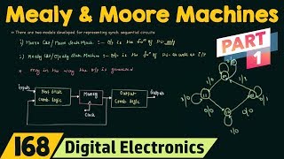
HDL Example (VHDL FSM Snippet)
This section describes a practical example of writing a hardware description language (HDL) code, specifically in VHDL, to illustrate how a finite state machine (FSM) operates. The process in the code snippet responds to a clock signal and a reset input.
Key Components of the Code:
- Process Statement: This encapsulates the logic that is executed on clock edges and resets.
- Reset Condition: When the reset signal is high (
'1'), the FSM returns to the initial state (S0). - State Transitions: On every rising edge of the clock (
rising_edge(clk)), the FSM transitions between states defined in a case statement, ensuring each state transitions to the next one in a predetermined sequence.
This snippet is crucial for understanding FSM behaviors in digital designs, showcasing how HDL can precisely define state transitions and conditions.
Youtube Videos


Audio Book
Dive deep into the subject with an immersive audiobook experience.
VHDL Process Overview
Chapter 1 of 1
🔒 Unlock Audio Chapter
Sign up and enroll to access the full audio experience
Chapter Content
process(clk, reset)
begin
if reset = '1' then
state <= S0;
elsif rising_edge(clk) then
case state is
when S0 => state <= S1;
when S1 => state <= S2;
when S2 => state <= S3;
when S3 => state <= S0;
end case;
end if;
end process;
Detailed Explanation
This chunk presents a VHDL process which is essential for designing an FSM. It defines how the system reacts to a clock signal and a reset signal.
- Process Declaration: The process starts with a declaration that it responds to two signals: the clock (
clk) and the reset (reset). This means any changes in these signals will trigger the execution of the code inside the process. - Reset Logic: The first conditional checks if the reset signal is activated (set to '1'). If so, the state is set to
S0, which usually represents a default or initial state. - State Transition on Clock Edge: The next part checks for a rising edge of the clock (indicating a clock pulse). If this happens and the reset is not active, it proceeds to evaluate the current state.
- State Case Statement: The
casestatement is used to switch between states. For each state (S0,S1,S2,S3), the process specifies the next state upon receiving a clock pulse. For example, if the current state isS0, it transitions toS1. - End of Process: The process concludes after defining all state transitions, ensuring the FSM cycles through its states correctly.
Examples & Analogies
Think of this VHDL snippet like a set of traffic lights. The clk acts like the timer that changes the lights, while the reset is akin to a manual switch that sets the lights back to red (S0). Just like the traffic light changes from red to green and then back to red again in a specific sequence, this snippet dictates how the FSM moves from one state to another based on the clock signal.
Key Concepts
-
VHDL: A hardware description language for digital circuit design.
-
FSM: A model that describes behavior in terms of states and transitions.
-
Process: A VHDL structure that encapsulates a sequence of operations responsive to signals.
-
State Transition: Movement from one state to another based on input conditions.
-
Reset: A signal that initializes the system back to its starting state.
Examples & Applications
An FSM for a vending machine can define states such as 'Idle', 'Selecting Item', and 'Dispensing'.
The control logic for an elevator can be represented as states like 'Moving Up', 'Moving Down', and 'Idle'.
Memory Aids
Interactive tools to help you remember key concepts
Rhymes
When the clock ticks, a state must shift, VHDL's powerful, it's our gift!
Stories
Imagine an elevator; it’s up and down, responding to the floor's call, but it needs a clever FSM to avoid a fall.
Memory Tools
R.E.C.A.P. - Reset, Evaluate clock, Change state, Assign output, Process done.
Acronyms
F.S.M. - Finite States Manage; focusing on the transitions you must plan.
Flash Cards
Glossary
- VHDL
VHSIC Hardware Description Language, a standard language for describing digital systems.
- FSM
Finite State Machine, a mathematical model of computation consisting of states and transitions.
- Process
A structure in VHDL that contains consecutive statements that describe the behavior of a digital circuit.
- State Transition
The change of the FSM from one state to another in response to input signals.
- Reset
A signal used to return the system to its initial state.
Reference links
Supplementary resources to enhance your learning experience.