
Design-for-Debugging Best Practices
Interactive Audio Lesson
Listen to a student-teacher conversation explaining the topic in a relatable way.
Adding Test Points or LEDs
🔒 Unlock Audio Lesson
Sign up and enroll to listen to this audio lesson

Today, we're discussing the first practice: adding test points or LEDs. Why do you think this can be beneficial?

To see if the circuit is working properly!
Exactly! They provide real-time feedback and help us identify issues quickly. It's a straightforward way to monitor functionality.

Could this help if something goes wrong during testing?
Yes, definitely! If an LED doesn't light up as expected, it can direct us to a specific area of the circuit that requires attention.

So, it's like a beacon guiding us to the problems?
That's a great way to put it! They guide us to the errors.

Can we also do this in simulation?
Absolutely! Simulations can also include test outputs to help visualize how the circuit will behave.
To summarize, adding test points or LEDs facilitates quick diagnostics and enhances our debugging process.
Modular Design
🔒 Unlock Audio Lesson
Sign up and enroll to listen to this audio lesson

Next, let’s discuss modular design. What do we understand by that term?
Is it about making the circuit in separate parts?
Correct! By creating subsystems, we can test each part individually, which simplifies troubleshooting. Who can give an example of modular design?
Like breaking a circuit down into an input section, logic section, and output section?
Exactly! This separation allows us to isolate faults more easily.
Does that mean we can also reuse these modules in future designs?
Yes! Reusability is another advantage, along with reduced debugging cycles.
So, in summary, modular design significantly improves our ability to isolate and test subsystems.
Labeling Signals
🔒 Unlock Audio Lesson
Sign up and enroll to listen to this audio lesson
Now, let's talk about labeling signals. Why is it essential in circuit design?
It makes it easier to identify which signal is which!
That's right! It speeds up the analysis and helps avoid confusion, especially when debugging. Can anyone think of a situation where poor labeling would cause issues?
If we have multiple signals that are similar in a complex circuit?
Exactly! Ambiguous labeling can lead to mistakes, making it difficult to troubleshoot effectively.
So, is it better to be overly descriptive?
Yes, detailed labeling helps everyone understand the circuit at a glance. In summary, good signal naming significantly enhances our debugging efficiency.
Clear Documentation
🔒 Unlock Audio Lesson
Sign up and enroll to listen to this audio lesson
Next, let’s discuss the role of clear documentation. Why is this necessary?
So others can understand the design and the choices made?
Precisely! Good documentation is crucial for team collaboration and revisiting projects in the future.
What kind of things should we document?
Diagrams, signal descriptions, design decisions, and even troubleshooting methods should all be included.
How about when we need to debug someone else's work?
Great point! Comprehensive documentation makes it easier to follow someone else's design logic and reduces troubleshooting time.
So, remember, keeping clear documentation is key to effective debugging and teamwork.
Introduction & Overview
Read summaries of the section's main ideas at different levels of detail.
Quick Overview
Standard
The section explores essential practices in digital circuit design that enhance the debugging process, such as adding test points, modular design, signal labeling, maintaining clear documentation, and using simulations before builds.
Detailed
Design-for-Debugging Best Practices
In digital circuit design, integrating debugging best practices from the onset can significantly ease the troubleshooting process later on. This section outlines crucial strategies that enhance the effectiveness and efficiency of debugging:
Key Practices
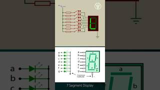
- Add Test Points or LEDs: Incorporating test points or indicators allows designers to visually monitor circuit operation and identify issues quickly.
- Modular Design: By creating subsystems that can be individually tested in isolation, it becomes easier to pinpoint the source of problems without dealing with a whole circuit at once.
- Label All Signals: Clearly labeling signals accelerates analysis, minimizing confusion during debugging as it aligns with better communication among team members.
- Maintain Clear Documentation: Good documentation serves as a critical reference during collaboration and when revisiting projects after an absence.
- Use Simulation Before Build: Simulating circuits prior to construction helps uncover logical errors and ensures that designs function as intended before physical implementation.
These practices not only save time and resources in troubleshooting but also instill a culture of excellence and reliability in digital design.
Youtube Videos
Audio Book
Dive deep into the subject with an immersive audiobook experience.
Adding Test Points or LEDs
Chapter 1 of 5
🔒 Unlock Audio Chapter
Sign up and enroll to access the full audio experience
Chapter Content
Practice: Add test points or LEDs
Benefit: Visual feedback during operation
Detailed Explanation
Adding test points or LEDs to your circuit allows you to visually monitor its behavior in real-time. When the circuit operates, the LEDs will light up or change states based on the activity in the circuit. This immediate visual feedback helps you quickly identify where issues may be occurring without needing extensive testing equipment.
Examples & Analogies
Think of these LEDs like the dashboard lights in a car. Just as the dashboard lights indicate whether the fuel level is low or if there’s an engine problem, LEDs in your circuit can show when things are functioning normally or if there’s a fault.
Modular Design
Chapter 2 of 5
🔒 Unlock Audio Chapter
Sign up and enroll to access the full audio experience
Chapter Content
Practice: Modular design
Benefit: Easier to isolate and test subsystems
Detailed Explanation
Modular design involves breaking your circuit into smaller, manageable subsystems. By doing so, you can focus on troubleshooting one module at a time rather than the entire system. This isolation makes it easier to test each part individually, facilitating quicker identification and resolution of issues.
Examples & Analogies
Imagine a large team project where everyone is responsible for a different part. If one part fails, it’s much easier to identify problems within an individual’s work instead of looking at the entire project. This focused approach in troubleshooting saves time and reduces frustration.
Labeling All Signals
Chapter 3 of 5
🔒 Unlock Audio Chapter
Sign up and enroll to access the full audio experience
Chapter Content
Practice: Label all signals
Benefit: Speeds up analysis
Detailed Explanation
Labeling all signals in your circuit schematic helps anyone reviewing or working on the circuit understand how each part interacts. It significantly speeds up the analysis phase during troubleshooting, as you spend less time trying to figure out what each wire or signal represents.
Examples & Analogies
Consider a map of a city. If the streets are not labeled, finding your way would be very challenging. Similarly, labeled signals in a circuit make it much easier to navigate and troubleshoot.
Maintaining Clear Documentation
Chapter 4 of 5
🔒 Unlock Audio Chapter
Sign up and enroll to access the full audio experience
Chapter Content
Practice: Maintain clear documentation
Benefit: Helpful for debugging and teamwork
Detailed Explanation
Documenting your design and any changes made during the process is crucial for effective debugging. Clear documentation allows anyone working on the project, including future team members, to understand the design decisions and the current state of the circuit, facilitating teamwork and repairs.
Examples & Analogies
Think of documentation like a recipe when cooking. If someone wants to recreate a dish, a clear recipe with ingredients and steps is essential. Without it, they may struggle to get the same result. Similarly, well-documented circuits lead to better understanding and troubleshooting capabilities.
Using Simulation Before Build
Chapter 5 of 5
🔒 Unlock Audio Chapter
Sign up and enroll to access the full audio experience
Chapter Content
Practice: Use simulation before build
Benefit: Catch logical errors early
Detailed Explanation
Simulating your circuit design before physically building it helps identify potential logic errors early in the design process. This preemptive troubleshooting can save a significant amount of time and resources, as fixing issues is usually easier in a simulation than in a physical setup.
Examples & Analogies
It's like using a flight simulator before piloting a real airplane. Pilots can practice and make mistakes in a low-risk environment without endangering lives or wasting fuel. Similarly, simulations allow you to find and fix issues without the costly implications of real hardware failure.
Key Concepts
-
Test Points: Critical for real-time feedback in debugging.
-
Modular Design: Eases the isolation and testing process.
-
Signal Labeling: Accelerates analysis and minimizes confusion.
-
Documentation: Essential for teamwork and future project reference.
Examples & Applications
Adding test points can help indicate the state of a circuit and thus highlight issues without extensive probing.
A modular-design approach allows for reusing the input stage of a circuit across different projects.
Memory Aids
Interactive tools to help you remember key concepts
Rhymes
Signal clear, avoid the fear, label right, to debug with light.
Stories
Once a circuit was built, but it fell ill. Test points were hardly seen, and confusion thrived until proper labeling brought back the thrill!
Memory Tools
P.L.A.D - Points (test), Label all signals, Assemble in modules, Document all details.
Acronyms
S.M.A.R.T - Signals labeled, Modular design, All details on paper, Ready for testing.
Flash Cards
Glossary
- Test Points
Designated points in a circuit where measurements can be taken to check functionality.
- Modular Design
Designing systems in separable units or modules to facilitate easier testing and debugging.
- Signal Labeling
The practice of naming signals clearly to enhance understandability and minimize confusion.
- Documentation
Written or digital records that provide details about the design, including diagrams and decision notes.
Reference links
Supplementary resources to enhance your learning experience.