
Step 1: Design Analog Low-Pass Filter
Interactive Audio Lesson
Listen to a student-teacher conversation explaining the topic in a relatable way.
Analog Filter Design
🔒 Unlock Audio Lesson
Sign up and enroll to listen to this audio lesson

Today, we're starting our discussion on designing analog low-pass filters. Can anyone tell me what they understand about low-pass filters?

Low-pass filters allow low frequencies to pass through while attenuating higher frequencies.
Correct! And in our case, we’re designing a first-order low-pass IIR filter with a specific cutoff frequency. Does anyone remember how we determine that?

Is it by using the transfer function?
Exactly! The transfer function we will use is H(s) = K/(τs + 1) where K is the gain. What is your guess for the typical value of K?

I think K is usually set to 1.
That’s right! Now, what about the time constant τ? How do we calculate that?

We can find τ by using τ = 1/(2πfc).
Great! Given our cutoff frequency of 1 Hz, let's calculate τ together.
Using the formula τ = 1/(2π×1), we find τ is approximately 0.159 seconds. Let's now plug this into our transfer function.
So our transfer function now becomes H(s) = 1/(0.159s + 1)?
Exactly! This function will guide us in designing our digital filter later.
To summarize, we learned how to derive the transfer function for a first-order low-pass filter and the significance of the time constant in relation to the cutoff frequency.
Introduction & Overview
Read summaries of the section's main ideas at different levels of detail.
Quick Overview
Standard
The section discusses how to create an analog low-pass IIR filter by establishing its transfer function, deriving the time constant based on the specified cutoff frequency, and simplifying the function to use in digital signal processing.
Detailed
In this section, we focus on the design of an analog low-pass filter as part of the IIR filter design process. We utilize the standard first-order low-pass filter transfer function in the s-domain, given by H(s) = K/(τs + 1), where K is the gain (usually set to 1) and τ is the time constant. The time constant is derived from the cut-off frequency using τ = 1/(2πfc), allowing us to evaluate τ at fc = 1 Hz, which results in τ ≈ 0.159 seconds. By substituting the values into the transfer function, we arrive at the analog filter’s transfer function H(s) = 1/(0.159s + 1), laying the foundation for further digital filter design methods later in the chapter.
Youtube Videos

Audio Book
Dive deep into the subject with an immersive audiobook experience.
Transfer Function of a Low-Pass Filter
Chapter 1 of 3
🔒 Unlock Audio Chapter
Sign up and enroll to access the full audio experience
Chapter Content
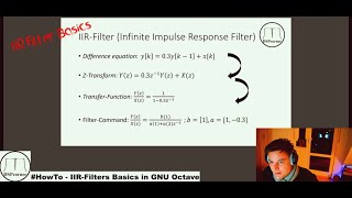
The first step is to design the analog low-pass filter. For this, we can use the standard first-order low-pass filter transfer function in the s-domain (analog):
H(s)=Kτs+1,
Where:
● K is the gain (typically K=1).
● τ is the time constant of the filter, related to the cutoff frequency by τ=12πfc.
Detailed Explanation
In filter design, an analog low-pass filter's behavior can be described using a transfer function. The typical first-order transfer function is represented as H(s) = K / (τs + 1). Here, K signifies the gain, which is most often set to 1 for simplicity. The time constant τ, determined by the cutoff frequency, defines how quickly the filter responds to changes in input signals.
Examples & Analogies
Think of the transfer function like a recipe. The gain K is the desired strength of a dish, while the time constant τ acts as the cooking time, controlling how quickly flavors mix. Just as a dish can be adjusted for better taste through different cooking times, a filter's response can be modified through its transfer function.
Calculating the Time Constant
Chapter 2 of 3
🔒 Unlock Audio Chapter
Sign up and enroll to access the full audio experience
Chapter Content
Given that the cutoff frequency fc=1 Hz, we can calculate the time constant τ:
τ=12π⋅1≈0.159 seconds.
Detailed Explanation
The time constant τ is a critical component in determining how the low-pass filter behaves. For a cutoff frequency of 1 Hz, calculating τ involves using the formula τ = 1 / (2πfc). By substituting the cutoff frequency into the formula, we find that τ is approximately 0.159 seconds. This value helps dictate the responsiveness of the filter to changes in the input signal.
Examples & Analogies
Imagine you are tuning a radio to hear your favorite station. If the station is too far away (i.e., high frequency), you won't hear it well (filtering effect). The time constant τ is like the antenna's ability to pick up signals; a lower τ means it can respond quickly, allowing you to hear low-frequency sounds (like soft music) more easily.
Transfer Function After Calculation
Chapter 3 of 3
🔒 Unlock Audio Chapter
Sign up and enroll to access the full audio experience
Chapter Content
So, the transfer function of the analog filter is:
H(s)=10.159s+1.
Detailed Explanation
After calculating the time constant, we can substitute it back into our transfer function. This yields H(s) = 1 / (0.159s + 1), providing us with a precise mathematical representation of our low-pass filter's behavior in the s-domain. This function indicates how the filter will respond to different frequencies it receives.
Examples & Analogies
Think about how an air filter works. If the filter is tuned correctly (i.e., transfer function is set properly), it effectively captures dust particles while allowing air to flow freely. The transfer function, in this analogy, is like describing how well the filter responds to various air particles during cleaning.
Key Concepts
-
Analog Low-Pass Filter: Allows low frequencies to pass while attenuating high frequencies.
-
Transfer Function: Mathematical expression representing the behavior of the filter.
-
Time Constant (τ): Determines how quickly the filter responds to changes in input.
Examples & Applications
An analog low-pass filter designed with a cutoff frequency of 1 Hz will permit signals below 1 Hz to pass through while attenuating those above.
Memory Aids
Interactive tools to help you remember key concepts
Rhymes
Low frequencies stay, high ones go away.
Stories
Imagine a stream where slow fish pass, while fast ones are filtered out, just like signals in a low-pass filter.
Memory Tools
K is the Key to filter gain; τ controls the time and frequency lane.
Acronyms
LPAF
Low-Pass Analog Filter.
Flash Cards
Glossary
- Analog Filter
An electronic filter that processes continuous-time signals.
- Cutoff Frequency (fc)
The frequency at which the output signal is reduced to a specified fraction of the input signal.
- Time Constant (τ)
A parameter that determines the speed of the filter’s response, inversely related to the cutoff frequency.
- Transfer Function
A mathematical representation in the s-domain that characterizes the input-output relationship of a filter.
Reference links
Supplementary resources to enhance your learning experience.