
Interfacing with Sensors and Actuators
Interactive Audio Lesson
Listen to a student-teacher conversation explaining the topic in a relatable way.
Introduction to Sensors and Actuators
🔒 Unlock Audio Lesson
Sign up and enroll to listen to this audio lesson

Today, we will discuss how sensors and actuators are interfaced with microcontrollers. Can anyone explain what a sensor does?

A sensor gathers information from the environment, like temperature or light.
Exactly! Sensors convert physical quantities into electrical signals. And how about actuators?

Actuators are devices that perform actions, like turning on a motor.
Correct! Together, they allow our microcontrollers to interact with the external world. Remember the acronym 'SENS' - Sensors gather Environmental data, Navigating Systems.

So every time we measure temperature or control a fan, we're using both?
Yes, exactly! They work together to achieve feedback control in various applications.
Types of Sensors
🔒 Unlock Audio Lesson
Sign up and enroll to listen to this audio lesson

Let's delve deeper into types of sensors. Can anyone differentiate between analog and digital sensors?
Analog sensors give continuous signals, like a voltage for temperature.
And digital sensors just give a binary signal, right?
Correct! Analog sensors, like the LM35, provide a signal proportional to the physical quantity, whereas digital sensors like the DHT11 yield discrete output. Remember 'A for Analog, D for Digital' to distinguish.
Can we use both in a system simultaneously?
Yes, using both in a control system can provide robust data monitoring and actuating strategy.
Analog-to-Digital Converter (ADC)
🔒 Unlock Audio Lesson
Sign up and enroll to listen to this audio lesson
Now, how do microcontrollers read values from sensors? Let's talk about ADC.

Isn’t it about converting analog signals to digital?
Absolutely! ADCs convert the analog voltage from sensors into digital values. What's an important factor of ADCs?
Resolution, higher bits mean more precision!
That's correct! Also, remember the sampling rate affects how quickly those values are read. Think of 'R-S' for Resolution and Sampling.
How does this affect our sensors?
Good question! It ensures that we capture changes accurately. Verify through fast-changing signals!
Actuator Control
🔒 Unlock Audio Lesson
Sign up and enroll to listen to this audio lesson
Moving on to actuators! What types do you think we have?
We have motors, servos, and relays.
Exactly! Motors can be DC or stepper and offer various control methods. What kind of control do DC motors generally use?
They use PWM to control speed by changing the voltage!
Very good! Remember, PWM allows precise speed control, so keep 'PWM' in mind for 'Precise Width Modulation'.
And how do we control direction?
We use an H-Bridge circuit. This allows current flow in both directions. It's crucial for bidirectional movement!
Challenges in Sensor and Actuator Interfacing
🔒 Unlock Audio Lesson
Sign up and enroll to listen to this audio lesson
Finally, let's talk about challenges! What are some issues we might face with sensor interfacing?
Signal noise might affect our readings.
That's right! We can use shielding and filtering methods to mitigate this noise. Also, power consumption is critical, especially in battery-operated devices.
How can we reduce that?
We can utilize sleep modes for sensors and adjust PWM signals. Remember 'N-P-S' for Noise, Power, and Signal strategies!
So, these challenges require clever solutions!
Exactly! And understanding these issues is vital for effective design.
Introduction & Overview
Read summaries of the section's main ideas at different levels of detail.
Quick Overview
Standard
Interfacing with sensors and actuators is vital for the functioning of embedded systems and IoT devices. This section covers types of sensors and actuators, their communication protocols, techniques for controlling them, and common challenges faced during interfacing.
Detailed
Interfacing with Sensors and Actuators
Interfacing with sensors and actuators is a crucial aspect of embedded systems and IoT devices, allowing for interaction with the external environment.
7.1 Introduction
Sensors gather data (e.g., temperature, light), and actuators perform physical actions (e.g., moving a motor). Proper interfacing entails using communication protocols and circuit design to process sensor data and optimize actuator control.
7.2 Principles of Sensor Interfacing
7.2.1 Types of Sensors
- Analog Sensors produce continuous signals proportional to measured quantities. Example: LM35 temperature sensor.
- Digital Sensors provide discrete outputs like high or low signals. Example: DHT11 digital sensor.
7.2.2 Analog-to-Digital Conversion (ADC)
Microcontrollers have built-in ADCs to read analog signals, converting them into digital values. Important factors include:
- Resolution: Quality of conversion (e.g., 8-bit vs. 10-bit).
- Sampling Rate: Frequency of sampling necessary for accurate readings.
7.2.3 Digital Sensors and Communication Protocols
Digital sensors communicate using protocols like I2C, SPI, or UART, allowing efficient data transfer to the microcontroller.
7.3 Actuator Control
Actuators perform actions based on signals received from microcontrollers through PWM or digital signals.
7.3.1 Types of Actuators
- DC Motors, Stepper Motors, Servo Motors: Provide various types of motion control.
- Relays: Control high-power devices based on microcontroller signals.
- LEDs and Lamps: Provide visual outputs for status indication.
7.3.2 Motor Control (DC Motor Example)
Controlled via PWM to adjust speed, usually implemented through H-Bridge circuits for direction control.
7.3.3 Servo Motor Control
Servos need precise pulse width signals for accurate position control.
7.4 Interfacing In Practical Applications
Examples include temperature control systems utilizing sensors and corresponding actuators to optimize conditions.
7.5 Common Challenges
- Signal Conditioning: Necessary for ensuring signals are accurate and clean.
- Power Consumption: Critical in battery-powered setups, requiring optimization strategies.
- Noise and Interference: Mitigation techniques such as shielding and software filtering must be adopted.
7.6 Summary of Key Concepts
The section synthesizes key ideas around sensor and actuator interfacing methods and the challenges encountered, providing a comprehensive overview necessary for effective embedded system design.
Youtube Videos
Audio Book
Dive deep into the subject with an immersive audiobook experience.
Introduction to Interfacing with Sensors and Actuators
Chapter 1 of 8
🔒 Unlock Audio Chapter
Sign up and enroll to access the full audio experience
Chapter Content
Interfacing sensors and actuators with microcontrollers is a critical aspect of embedded systems and IoT devices. Sensors allow the system to collect data from the environment, such as temperature, light intensity, or motion, while actuators enable the system to take physical actions, such as moving a motor or turning on a light. Interfacing these devices with microcontrollers involves using appropriate communication protocols and designing circuits to process sensor data and control actuators effectively. In this chapter, we will explore the principles of sensor interfacing with microcontrollers, various types of sensors and actuators, and methods for controlling and implementing actuator systems.
Detailed Explanation
This section introduces the fundamental concepts of interfacing sensors and actuators with microcontrollers. Sensors are devices that gather data about the physical world, while actuators are responsible for performing actions based on that data. The chapter will discuss how these components communicate with microcontrollers using protocols and circuit designs that allow them to function together within embedded systems and IoT applications.
Examples & Analogies
Imagine a smart thermostat for your home. The temperature sensor detects the current room temperature (the data-gathering part), and based on this reading, the actuator (like a heating system) adjusts the environment by turning the heat on or off. This shows how sensors provide information, and actuators use that information to take action.
Types of Sensors
Chapter 2 of 8
🔒 Unlock Audio Chapter
Sign up and enroll to access the full audio experience
Chapter Content
Sensors are devices that convert physical quantities (e.g., temperature, pressure, light) into electrical signals that can be read by a microcontroller. Sensors typically produce analog or digital signals.
- Analog Sensors: These sensors provide continuous, variable output that is proportional to the physical quantity they measure. For example, an analog temperature sensor (like an LM35) gives an output voltage that corresponds to the temperature.
- Digital Sensors: These sensors provide a discrete signal, usually in the form of a high (1) or low (0) state. For example, a digital temperature sensor (like the DHT11) directly gives temperature readings in a digital format.
Detailed Explanation
This chunk outlines the different types of sensors used to convert physical phenomena into signals that microcontrollers can process. Analog sensors continuously vary their output based on measurements, while digital sensors offer binary results, allowing for simplified data processing. Understanding the difference between these types is essential for selecting the appropriate sensor for a specific application.
Examples & Analogies
Consider a dimmer switch for lights in a room. An analog light sensor might vary its output based on the intensity of light coming in, like how a dimmer would adjust brightness smoothly. On the other hand, a digital light sensor acts like an on/off switch, only telling you whether it’s bright enough to trigger the lights or not.
Analog-to-Digital Conversion (ADC)
Chapter 3 of 8
🔒 Unlock Audio Chapter
Sign up and enroll to access the full audio experience
Chapter Content
Many microcontrollers, such as AVR, PIC, and ARM Cortex based devices, have built-in Analog-to-Digital Converters (ADCs) that allow them to read analog signals from sensors. ADCs convert the analog voltage from the sensor into a digital value that the microcontroller can process.
- Resolution: ADC resolution defines the precision of the conversion, typically measured in bits. For example, an 8-bit ADC provides 256 possible values (0-255), while a 10-bit ADC provides 1024 possible values (0-1023).
- Sampling Rate: The rate at which the ADC samples the analog input. Higher sampling rates are required for fast-changing signals, such as those from sensors in motion or temperature sensors.
Detailed Explanation
In this section, we discuss how microcontrollers convert analog signals from sensors into digital values using Analog-to-Digital Converters (ADCs). The resolution of an ADC determines how accurately it can represent a signal, while the sampling rate indicates how often the sensor's signal is read. Understanding these factors is crucial for effective sensor data processing, especially in applications that involve changing conditions.
Examples & Analogies
Think of ADC as a translator. If you are a tourist in a foreign country trying to understand the local language (the analog signal), the translator helps interpret it into your language so you can understand it better (digital signal). The resolution is like the clarity of the translation—how accurately can the translator express what the local is saying? The sampling rate is like how quickly the translator can provide translations as conversations happen; if it’s too slow, you might miss important cues.
Digital Sensors and Communication Protocols
Chapter 4 of 8
🔒 Unlock Audio Chapter
Sign up and enroll to access the full audio experience
Chapter Content
Digital sensors often communicate with microcontrollers using communication protocols such as I2C, SPI, or UART. These protocols allow sensors to send digital data to the microcontroller for further processing.
- I2C (Inter-Integrated Circuit): A two-wire protocol that allows multiple devices to communicate over a shared bus. It is commonly used for sensors like accelerometers, gyroscopes, and environmental sensors.
- SPI (Serial Peripheral Interface): A high-speed, four-wire protocol often used for faster data transfer between the microcontroller and sensors like digital temperature sensors or barometric pressure sensors.
- UART (Universal Asynchronous Receiver/Transmitter): A serial communication protocol used for transmitting data over two wires, commonly used for communication with GPS modules, Bluetooth devices, or wireless sensors.
Detailed Explanation
This segment explains how digital sensors connect with microcontrollers using various communication protocols. Each protocol has unique advantages; I2C allows multiple devices to communicate on a shared line, SPI is much faster for devices that require quick data transfers, and UART is used for simpler, straightforward communication. Understanding protocol characteristics helps in designing efficient embedded systems.
Examples & Analogies
Imagine a postal service system (UART), where each house (device) receives and sends letters (data) one at a time. Now think of a bustling market (I2C) where multiple vendors (devices) exchange goods with each other in a connected way. Lastly, think of a fast-moving delivery truck (SPI) that rapidly transports packages from one point to another without stopping to chat. Each method serves the purpose of communication but does so differently depending on the speed and requirements.
Actuator Control and Implementation
Chapter 5 of 8
🔒 Unlock Audio Chapter
Sign up and enroll to access the full audio experience
Chapter Content
Actuators are devices that perform actions based on the signals they receive from a microcontroller. The most common actuators include motors, servos, relays, and lights. Actuators generally operate using digital or PWM (Pulse Width Modulation) signals.
Detailed Explanation
This chunk defines what actuators are and their role in a microcontroller-based system. Actuators execute physical actions like moving motors or turning on lights based on commands they receive from the microcontroller. The mention of PWM highlights how fine control can be applied, particularly for speed and intensity adjustments.
Examples & Analogies
Consider a simple remote-controlled car. The motor acts as the actuator, enabling movement based on signals sent from the remote (microcontroller). When the 'forward' button is pressed, the car moves forward; when the speed control is adjusted via PWM, it varies how fast the car goes, illustrating how actuators bring digital signals to life physically.
Types of Actuators
Chapter 6 of 8
🔒 Unlock Audio Chapter
Sign up and enroll to access the full audio experience
Chapter Content
Actuators can be divided into several common types:
- Motors: Motors are used to provide motion. They can be of various types, including:
- DC Motors: Provide continuous rotation when powered.
- Stepper Motors: Provide precise, controllable rotation steps.
- Servo Motors: Provide precise control over angular position and are commonly used in robotics and automation.
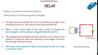
- Relays: Electromechanical switches that allow the microcontroller to control high-power devices such as lights, fans, or motors.
- LEDs and Lamps: Light-emitting diodes (LEDs) or lamps are simple actuators used to display status or provide visual feedback.
Detailed Explanation
This section provides a closer look at the different types of actuators used in embedded systems. It categorizes actuators primarily into motors, relays, and lights, explaining how each works and their applications. By knowing these types, one can choose the best actuator for specific tasks in their projects.
Examples & Analogies
Think about how we can control different things in our daily lives: the DC motor is like a regular fan—that just spins when you turn it on. A stepper motor is like a clock's second hand, moving precisely at each tick. Servos can be likened to a robotic arm, which only moves to specific angles when commanded, while relays can be thought of as light switches that control multiple lights. LEDs serve a purpose similar to indicator lights on your devices, letting you know when something is running or off.
Motor Control (DC Motor Example)
Chapter 7 of 8
🔒 Unlock Audio Chapter
Sign up and enroll to access the full audio experience
Chapter Content
DC motors require a controlled voltage or current to rotate. A common method for controlling DC motors in embedded systems is through Pulse Width Modulation (PWM), which allows the microcontroller to adjust the speed of the motor by varying the duty cycle of the PWM signal.
- H-Bridge Circuit: To control the direction of a DC motor, an H-Bridge circuit can be used. It allows the current to flow in both directions through the motor, enabling forward and reverse movement.
Detailed Explanation
In this section, we see how DC motors can be controlled using PWM for speed adjustments and an H-Bridge circuit for direction changes. The PWM signal allows the control of the voltage supplied to the motor, and the H-Bridge facilitates bidirectional movement. This knowledge is crucial for applications requiring precise motor control.
Examples & Analogies
Picture a car's accelerator pedal. Just as pressing the pedal increases the car’s speed (control through PWM), an H-Bridge allows the driver to not only speed up but also reverse the car's direction. Whenever you turn the wheel to go backward, the system doesn’t simply stop; it adjusts to drive in reverse, reflecting how H-Bridge circuits work.
Common Challenges in Sensor and Actuator Interfacing
Chapter 8 of 8
🔒 Unlock Audio Chapter
Sign up and enroll to access the full audio experience
Chapter Content
Many sensors, especially analog ones, may not provide signals in a form directly suitable for the microcontroller. Signal conditioning circuits like amplifiers, filters, and converters may be required to ensure the signal is within the microcontroller’s acceptable range.
- Power Consumption: Sensors and actuators can consume significant power, especially in battery-operated systems. Techniques like sleep modes for sensors and PWM control for actuators (to reduce energy consumption) can help optimize power usage.
- Noise and Interference: Sensor signals, especially in noisy environments, can be susceptible to interference. Using shielded cables, low-pass filters, and software filtering techniques (such as averaging or smoothing) can help mitigate this problem.
Detailed Explanation
This section discusses the challenges faced while interfacing sensors and actuators. Signal conditioning is necessary to ensure sensors provide usable outputs. Power consumption is critical in battery-operated devices, and strategies are highlighted. Lastly, noise interference poses significant issues, especially in complex environments, emphasizing the need for protective measures.
Examples & Analogies
Imagine trying to have a conversation in a crowded cafe (the noisy environment). You may need to lean closer to hear your friend (signal conditioning) and sometimes take breaks to catch your breath (power management). If there's a subpar connection due to distractions (noise), you start misinterpreting what your friend says. This analogy highlights how complicated it is to ensure clear communication between devices in embedded systems.
Key Concepts
-
Sensor Interfacing: The method of connecting sensors to microcontrollers to gather data.
-
Actuator Control: Techniques used to drive actuators based on sensor input.
-
Communication Protocols: I2C, SPI, and UART used for data transfer between devices.
-
Analog vs. Digital Sensors: Differences in signal types and applications.
-
Power Management: Techniques to minimize power consumption in sensors and actuators.
Examples & Applications
Interfacing an LM75 temperature sensor with an Arduino via I2C to read temperature data.
Using PWM to control a DC motor for varying speed in a robotic arm.
Memory Aids
Interactive tools to help you remember key concepts
Rhymes
Sensors gather data with ease, Actuators act like a breeze!
Stories
Imagine a smart home: A temperature sensor detects heat. When the room gets warm, the fan activates to cool you down, showing how sensors and actuators work hand in hand.
Memory Tools
SENS: Sensors gauge, Environment sensed, Navigate actions, Systems respond.
Acronyms
H-Bridge
Helps a motor change direction back and forth!
Flash Cards
Glossary
- ADC
Analog-to-Digital Converter, a device that converts analog signals to digital for processing.
- PWM
Pulse Width Modulation, a technique to control the speed of motors by varying the duty cycle.
- I2C
Inter-Integrated Circuit, a two-wire communication protocol used for connecting devices.
- SPI
Serial Peripheral Interface, a four-wire communication protocol for fast data transfer.
- Servo Motor
A type of motor that provides precise control over angular position.
- HBridge
A circuit that allows a motor to be driven in both directions.
- Digital Sensor
A sensor that provides discrete signals indicating the measured quantity.
- Analog Sensor
A sensor that provides a continuous signal proportionate to the measured physical quantity.
Reference links
Supplementary resources to enhance your learning experience.