
Wire Bonding
Interactive Audio Lesson
Listen to a student-teacher conversation explaining the topic in a relatable way.
Introduction to Wire Bonding
🔒 Unlock Audio Lesson
Sign up and enroll to listen to this audio lesson

Welcome class! Today, we're diving into wire bonding. Can anyone tell me what the primary purpose of wire bonding is in semiconductor packaging?

Isn't it to connect the IC to the PCB?
Exactly! Wire bonding establishes electrical connections between integrated circuits and printed circuit boards. It’s crucial for ensuring the functionality of the IC. Now, what materials are typically used in wire bonding?

Gold and aluminum, right?
Correct! Gold is often used for its low resistivity and corrosion resistance, while aluminum is chosen for its cost-effectiveness. Remember the acronym GAC: Gold for high reliability, Aluminum for affordability, and Copper for high-speed applications!

What about the process? How does wire bonding work?
Great question! During wire bonding, we heat a wire and press it against the lead frame to create a 'ball bond' at the die. The wire is then stretched to form a 'wedge bond' at the PCB. This connection is key to delivering electrical signals. Remember: 'Ball-to-Wedge' is the bonding process!
Applications of Wire Bonding
🔒 Unlock Audio Lesson
Sign up and enroll to listen to this audio lesson

Now that we understand the process, let's talk about applications. Where do you think wire bonding is commonly used?

I think it's used in consumer electronics!
Absolutely! It's widely used in dual-in-line packages (DIP), surface-mount devices (SMD), and small-outline packages (SOP). Why do you think it’s favored for these applications?
Because it’s cost-effective?
Yes! Its low cost and high throughput make wire bonding ideal for mass production. It’s about balancing cost and efficiency here. Does anyone see any drawbacks?
It might not work well for high-speed applications due to inductance?
That's spot on! The longer wire lengths can be detrimental in high-frequency situations. Let's summarize: wire bonding is cost-effective but has limitations in high-speed environments.
Advantages and Disadvantages of Wire Bonding
🔒 Unlock Audio Lesson
Sign up and enroll to listen to this audio lesson
Let’s take a moment to weigh the advantages and disadvantages of wire bonding. Can someone share an advantage?
It has a low cost for mass production?
Exactly! Its affordability is crucial for high-volume production. Now, what about a disadvantage?
It can be affected by mechanical stress, right?
Correct! Mechanical stress can lead to failures. Remember: 'Cost vs. Stability' is key in our evaluation of wire bonding. Does that make sense?
High-Speed Applications and Wire Bonding Limitations
🔒 Unlock Audio Lesson
Sign up and enroll to listen to this audio lesson
Lastly, let’s discuss high-speed applications. Why is wire bonding not suitable for all?
Because of the longer wire lengths that increase inductance?
Exactly! Higher inductance can lead to signal integrity issues in high-frequency environments. It’s important to be aware of the scenarios where wire bonding may not be the best choice.
What alternatives do we have for high-speed applications?
Great question! Alternatives include flip-chip technology, which minimizes interconnection lengths and enhances performance. Remember to always consider your application's needs!
Introduction & Overview
Read summaries of the section's main ideas at different levels of detail.
Quick Overview
Standard
Wire bonding is an essential interconnection technique utilized in semiconductor packaging. It employs fine gold or aluminum wires to create connections between the IC leads and the PCB, making it suitable for mass production due to its cost-effectiveness. However, it faces limitations in high-speed applications because of longer wire lengths causing higher inductance.
Detailed
In-Depth Summary of Wire Bonding
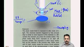
Wire bonding is the most widely used interconnection method in semiconductor packaging, crucial for establishing electrical connections between integrated circuits (ICs) and printed circuit boards (PCBs) or packages. The wire bonding process involves heating and pressing a wire—either gold or aluminum—against the IC lead frame, forming a ball bond, and then stretching it to the PCB for wedge bonding.
This technique is often favored in dual-in-line packages (DIP), surface-mount packages (SMD), and small-outline packages (SOP) due to its low cost and high throughput, making it ideal for applications with high volume and an emphasis on cost efficiency.
Advantages
- Economical for large-scale production.
- Versatile across various IC types, including logic chips and power devices.
Disadvantages
- Limited performance in high-speed or high-frequency applications due to higher inductance from longer wire lengths.
- Vulnerable to mechanical stress and vibration, potentially impacting reliability.
Elevating the understanding of wire bonding involves recognizing its significance in the broader context of semiconductor packaging, linking material choice and technology to device performance and reliability.
Youtube Videos
Audio Book
Dive deep into the subject with an immersive audiobook experience.
Overview of Wire Bonding
Chapter 1 of 5
🔒 Unlock Audio Chapter
Sign up and enroll to access the full audio experience
Chapter Content
Wire bonding is the most common interconnection technique used in semiconductor packaging. In wire bonding, fine wires are used to establish electrical connections between the IC leads and the pins or pads of the PCB or package.
Detailed Explanation
Wire bonding is a method where very thin wires, usually made of gold or aluminum, are used to connect the inside of semiconductor chips (ICs) to the outside pins or pads on the package or PCB. This process is essential because it allows electrical signals to travel in and out of the semiconductor device, enabling it to function. Think of wire bonding as the electrical 'wires' that allow communication within a circuit, similar to how wires in your house allow electricity to flow to different rooms.
Examples & Analogies
Imagine a complex city where various neighborhoods are connected by roads. Each neighborhood represents a semiconductor chip, and the roads represent the wire bonds. Just like how roads are essential for transportation between neighborhoods, wire bonds are crucial for electrical signals to move between the IC and the outside world.
The Bonding Process
Chapter 2 of 5
🔒 Unlock Audio Chapter
Sign up and enroll to access the full audio experience
Chapter Content
During the bonding process, a gold or aluminum wire is heated and pressed against the lead frame or pad, forming a ball bond at the die, and then stretched to the lead frame or PCB for wedge bonding.
Detailed Explanation
The bonding process begins by creating a small 'ball' at the end of a wire made from materials like gold or aluminum. This ball is then positioned to touch the lead frame or a pad on the IC die. Heat and pressure are applied, causing the ball to fuse with the pad, forming a strong connection known as a ball bond. After this, the wire is stretched out to connect with another pad on the PCB, creating a wedge bond. This two-step process ensures a secure and reliable connection for the electrical signals to flow.
Examples & Analogies
Think of making a strong connection between two pieces of clay. First, you create a small blob of clay (the ball bond) and press it against another piece before stretching it out to tap into another area (the wedge bond). Just like these steps ensure the clay pieces stick well together, the bonding process helps establish reliable electrical connections.
Applications of Wire Bonding
Chapter 3 of 5
🔒 Unlock Audio Chapter
Sign up and enroll to access the full audio experience
Chapter Content
Wire bonding is widely used in dual-in-line packages (DIP), surface-mount packages (SMD), and small-outline packages (SOP). It is the preferred method for applications where high volumes and cost efficiency are critical.
Detailed Explanation
Wire bonding is frequently utilized in various semiconductor packaging types, including DIP, SMD, and SOP. These package types determine how the ICs are mounted and connected to the circuit boards. Wire bonding is favored in many high-volume production scenarios because it is cost-effective and efficient. Manufacturers often choose this technique when producing large quantities of devices as it allows them to keep costs lower while still meeting performance requirements.
Examples & Analogies
Consider a bakery producing hundreds of cupcakes. They often use a standard recipe and technique that is efficient for large batches. Wire bonding functions similarly in the semiconductor industry, offering a reliable and cost-effective way to produce a high volume of electronic components for various applications.
Advantages of Wire Bonding
Chapter 4 of 5
🔒 Unlock Audio Chapter
Sign up and enroll to access the full audio experience
Chapter Content
• Low cost and high throughput make it ideal for mass production.
• Suitable for a wide variety of ICs, including logic chips, memory chips, and power devices.
Detailed Explanation
One of the significant benefits of wire bonding is its low cost, which makes it an attractive option for mass production of semiconductor devices. The high throughput of the process means that many devices can be manufactured in a short amount of time without sacrificing quality. Additionally, wire bonding can be used for different types of ICs, which adds to its versatility in the industry.
Examples & Analogies
Think of wire bonding like using a standard assembly line in a factory. Just as factories use assembly lines to produce more goods at a lower cost, wire bonding allows semiconductor manufacturers to produce electronic components efficiently and affordably, making it a go-to method in the field.
Disadvantages of Wire Bonding
Chapter 5 of 5
🔒 Unlock Audio Chapter
Sign up and enroll to access the full audio experience
Chapter Content
• Limited performance in high-speed, high-frequency, and high-power applications due to longer wire lengths and higher inductance.
• Susceptibility to mechanical stress and vibration in certain applications.
Detailed Explanation
Despite its advantages, wire bonding has some drawbacks. One of the significant limitations is related to performance. Because wire lengths can be longer in this technique, they can introduce higher inductance, which may affect the performance of high-speed and high-frequency applications. Furthermore, wire bonds can be sensitive to physical forces like vibrations, which might weaken the connection and impact device reliability.
Examples & Analogies
Imagine a tightrope walker. If the tightrope is too long and slacks, it becomes more challenging for the walker to maintain balance. Similarly, in wire bonding, longer wires can lead to performance issues. Additionally, if the tightrope is wobbly or exposed to wind, the walker may fall, just as wire bonds can suffer from external stress, weakening the connection.
Key Concepts
-
Wire Bonding: A method for establishing electrical connections between ICs and PCBs using fine wires.
-
Ball and Wedge Bonds: The two types of bonds formed during the wire bonding process.
-
Cost Efficiency: Wire bonding is favored for low-cost, high-volume production.
-
Limitations: Performance issues in high-speed applications due to wire length and inductance.
Examples & Applications
In consumer electronics, wire bonding is frequently used to connect ICs in smartphones and other devices.
Wire bonding is the preferred method in dual-in-line packages (DIP) due to its cost-effectiveness.
Memory Aids
Interactive tools to help you remember key concepts
Rhymes
Wire bonding so fine, connects like a line, signals flow bright, making devices light!
Stories
Imagine a tiny highway where ICs send signals down wires. The longer the journey, the slower things get, making wire bonding great—just keep it short!
Memory Tools
Remember GAC: Gold, Aluminum, Copper for wire bonding; which materials to choose for speed or cost?
Acronyms
BOW
Ball and Wedge are the two types of bonds in wire bonding!
Flash Cards
Glossary
- Wire Bonding
An interconnection technique using fine wires to connect semiconductor ICs to their packages or PCBs.
- Ball Bond
The initial bond created at the IC die during the wire bonding process.
- Wedge Bond
The bond formed by stretching the wire from the ball bond to the PCB or package.
- Inductance
The tendency of an electrical conductor to oppose a change in the flow of current, significant in high-speed applications.
Reference links
Supplementary resources to enhance your learning experience.