
Introduction to Key Concepts – Power Consumption, Efficiency, and Trade-offs in CMOS and FinFET Technologies
Enroll to start learning
You’ve not yet enrolled in this course. Please enroll for free to listen to audio lessons, classroom podcasts and take practice test.
Interactive Audio Lesson
Listen to a student-teacher conversation explaining the topic in a relatable way.
Power Consumption Components
🔒 Unlock Audio Lesson
Sign up and enroll to listen to this audio lesson

Today, we will learn about power consumption components in CMOS and FinFET logic circuits. Can anyone tell me what dynamic power is?

Isn’t dynamic power related to how often the circuit switches?
Exactly! Dynamic power is calculated as P_dyn = αCLV_dd²f, where α is the activity factor. Who remembers what CL and V_dd stand for?

CL is load capacitance, and V_dd is the supply voltage!
Great job! Now, dynamic power becomes significant as the clock frequency increases. Let's also consider static power. Can anyone explain what it entails?

It involves leakage current when the device is not actively switching.
Correct! It’s crucial for scaling, especially as we approach sub-45nm technologies where leakage can become quite significant. Now, let's summarize what we learned about the three types of power: dynamic, short-circuit, and static power.
Efficiency Metrics
🔒 Unlock Audio Lesson
Sign up and enroll to listen to this audio lesson

Now that we’ve covered power components, let’s discuss efficiency metrics used to measure energy usage in circuits. Who can tell me what energy efficiency in digital circuits is measured by?

Energy per operation!
Yes! Lower energy per operation means more efficient designs. What about the power-delay product, or PDP?
Isn’t that the product of power and the time delay?
Absolutely! It shows the trade-off between power and speed. Lastly, can anyone explain the energy-delay product or EDP?
It’s the product of energy and time delay, right? It helps optimize circuits for performance-per-watt.
Exactly! A lower EDP indicates a more efficient design. Let’s summarize the efficiency metrics: energy per operation, PDP, and EDP.
CMOS vs. FinFET Comparison
🔒 Unlock Audio Lesson
Sign up and enroll to listen to this audio lesson
Now, let’s compare CMOS and FinFET technologies. What key differences can you think of between these two technologies?
FinFETs have better electrostatics, so they perform better at smaller nodes.
That's right! FinFETs show lower leakage at smaller manufacturing processes compared to CMOS. What about dynamic power?
FinFETs operate at lower supply voltages, reducing dynamic power further.
Exactly. While CMOS is cheaper due to mature fabrication, FinFETs may result in significant power savings at the same performance levels. Can anyone summarize which technology performs better in which aspect?
CMOS is easier and cheaper to manufacture, while FinFET offers better performance and energy efficiency!
Great summary! Always keep these trade-offs in mind when considering design choices.
Design Trade-offs
🔒 Unlock Audio Lesson
Sign up and enroll to listen to this audio lesson
Designing low-power circuits involves some critical trade-offs. Can anyone list some of these trade-offs?
Like power versus performance?
Yes! Reducing supply voltage decreases dynamic power but can also reduce speed. Any others?
Area against power is another one. If we parallelize circuits, we can reduce power but increase area.
Bingo! FinFETs occupy more area than CMOS but help reduce leakage. There’s also reliability versus efficiency and cost versus efficiency. Can someone explain these?
Near-threshold computing reduces power but makes the circuit sensitive to noise.
Exactly! Let’s wrap up by summarizing the major design trade-offs: balancing power, performance, area, reliability, and cost.
Introduction & Overview
Read summaries of the section's main ideas at different levels of detail.
Quick Overview
Standard
The section discusses power consumption components, efficiency metrics, and key trade-offs engineers face when designing circuits with CMOS and FinFET technologies. It explains the importance of balancing dynamic power, leakage, area, cost, and performance in the context of advancing technology.
Detailed
Detailed Summary
This section provides an overview of critical concepts related to power consumption and energy efficiency in CMOS and FinFET technologies, which are essential for designing low-power digital and mixed-signal systems. It begins by identifying the core problem of managing power consumption while balancing factors such as speed, functionality, leakage, area, and cost as circuit complexity increases.
Power Consumption Components
It breaks down power consumption into dynamic power, short-circuit power, and static (leakage) power. Dynamic power, which relates to switching activity, is expressed with an equation that incorporates load capacitance, supply voltage, clock frequency, and activity factor. Short-circuit power is introduced briefly regarding its momentary occurrence during gate transitions, while static power is detailed in terms of its significance at smaller manufacturing processes.
Efficiency Metrics
Efficiency metrics include energy per operation, power-delay product, and energy-delay product, each providing insights into design efficiency and trade-offs. A focus on these metrics helps engineers optimize circuit performance without compromising power consumption.
CMOS vs FinFET Comparison
A direct comparison of CMOS and FinFET technologies is presented to illustrate their handling of power and efficiency. FinFETs are noted for their improved energy efficiency and reduced leakage despite higher costs and complexity.
Design Trade-offs
Design trade-offs are explored, highlighting how engineers must balance power against performance, area against power, reliability against efficiency, and cost against efficiency to arrive at optimal circuit designs. Understanding these constraints is crucial for tailored applications in mobile devices, servers, and IoT systems.
Youtube Videos


Audio Book
Dive deep into the subject with an immersive audiobook experience.
Introduction to Key Concepts
Chapter 1 of 7
🔒 Unlock Audio Chapter
Sign up and enroll to access the full audio experience
Chapter Content
This chapter introduces the fundamental concepts of power consumption, energy efficiency, and design trade-offs in CMOS and FinFET-based circuits. Understanding these parameters is essential for optimizing low-power digital and mixed-signal systems. While CMOS has been the backbone of low-power logic for decades, FinFETs have emerged as a solution to overcome limitations in leakage and scaling.
We will compare how these two technologies handle power dissipation, explore metrics for measuring energy efficiency, and understand the trade-offs engineers must consider in advanced designs.
Detailed Explanation
This section introduces the basic ideas related to power consumption, efficiency in energy use, and the trade-offs that engineers face when using two types of technology: CMOS and FinFET. It highlights that power consumption is crucial for designing circuits that are efficient and low-power, especially as technology progresses. CMOS has traditionally been a popular choice, but FinFET is introduced as a newer option that can address certain problems related to power leakage and scaling down of devices. The chapter aims to delve deeper into comparing these technologies regarding how they manage power, how to measure their efficiency, and the various considerations engineers must account for in their designs.
Examples & Analogies
Think of power consumption and efficiency in a household setting. Just as families look for energy-efficient appliances to reduce electricity bills while maintaining performance, engineers seek to optimize circuits in a similar way. CMOS appliances can be compared to traditional devices that are cheaper but might consume more power, whereas FinFETs are akin to newer, more expensive, but efficient appliances that save energy over time.
Problem Statement
Chapter 2 of 7
🔒 Unlock Audio Chapter
Sign up and enroll to access the full audio experience
Chapter Content
As circuit complexity grows and devices shrink, designers must:
● Minimize power without sacrificing speed or functionality.
● Balance dynamic power, leakage, area, and cost.
● Evaluate how CMOS and FinFET behave differently under these constraints.
The challenge is to optimize designs for specific use cases (e.g., mobile, server, IoT) while understanding the inherent trade-offs in each technology.
Detailed Explanation
This section presents the challenges faced by designers as technology evolves. With devices becoming smaller and more complex, engineers need to find ways to reduce power consumption without losing the speed or functionality of the circuits. They have to carefully consider various factors such as dynamic power (the power used during operation), leakage power (energy lost when a circuit is idle), the physical area the circuit occupies, and overall costs. Also, understanding the differences in performance between CMOS and FinFET becomes critical, as each technology has its own strengths and weaknesses. Ultimately, engineers must tailor their designs based on the specific requirements of their target applications, such as mobile devices, servers, or Internet of Things (IoT) devices.
Examples & Analogies
Imagine baking a cake: the goal is to make a delicious cake (functionality) while using as little energy as possible (minimizing power). You can lower the oven temperature (dynamic power) to save energy, but that might take longer to bake (sacrificing speed). Similarly, you have to manage ingredients (area and cost) wisely to keep your cake affordable but still tasty. Just like bakers adjust their recipes for special occasions, engineers need to adapt their designs to different technology needs.
Power Consumption Components in Circuits
Chapter 3 of 7
🔒 Unlock Audio Chapter
Sign up and enroll to access the full audio experience
Chapter Content
In CMOS and FinFET logic circuits, total power (P_total) is divided into:
1. Dynamic Power (Switching Power):
Pdyn=αCLVdd2f
○ α: Activity factor (switching probability)
○ CL: Load capacitance
○ Vdd: Supply voltage
○ f: Clock frequency
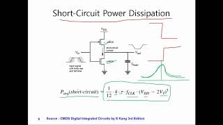
2. Short-Circuit Power:
○ Occurs during gate transitions when both PMOS and NMOS conduct momentarily.
○ Generally a small part of total power but grows with Vdd and transition time.
3. Static (Leakage) Power:
Pleak=Ileak⋅Vdd
○ Becomes significant in deep submicron processes (90nm and below).
○ Includes subthreshold leakage, gate oxide leakage, and junction leakage.
Detailed Explanation
This section breaks down the total power consumption in circuits into three main types: dynamic power, short-circuit power, and static (leakage) power. Dynamic power, which is the power used when a circuit is actively switching states, is influenced by several factors like the activity factor, load capacitance, supply voltage, and clock frequency. Short-circuit power occurs during the momentary conduction of both types of transistors (PMOS and NMOS) during state changes and contributes a smaller but growing portion of total power consumption. Finally, static power—especially leakage power—becomes crucial in smaller fabrication processes, as it accounts for energy that is lost even when the circuit is not actively switching. Understanding these components helps engineers design more efficient circuits by targeting areas where power can be reduced.
Examples & Analogies
Consider a car using fuel. The dynamic power can be likened to fuel consumed when the car is accelerating. Short-circuit power is like the fuel wasted when the engine is running but the car is stationary—an inefficiency that can be minimized. Static power resembles the fuel that evaporates from the gas tank when it's just sitting there, not moving. Each type of fuel consumption offers insights into how we can make the car (or circuit) run more efficiently.
Efficiency Metrics
Chapter 4 of 7
🔒 Unlock Audio Chapter
Sign up and enroll to access the full audio experience
Chapter Content
Energy Efficiency in digital circuits is measured using several key metrics:
● Energy per Operation:
E = P⋅t
Lower energy per task = more efficient design.
● Power-Delay Product (PDP):
PDP = P⋅tdelay
Indicates trade-off between power and speed.
● Energy-Delay Product (EDP):
EDP = E⋅tdelay = P⋅tdelay2
Helps optimize circuits for performance-per-watt.
A lower EDP signifies a more energy-efficient and faster design.
Detailed Explanation
In this section, we discuss the primary metrics used to gauge energy efficiency in digital circuits. The first is energy per operation, which refers to the total energy consumed by a circuit to perform a task. The lower this energy usage, the more efficient the design is considered. The power-delay product (PDP) assesses the relationship between power consumption and speed—the faster a circuit can process operations while consuming less power, the better. Lastly, the energy-delay product (EDP) takes into account both energy and delay to indicate how well a circuit performs on a per-watt basis. A lower EDP means higher energy efficiency and faster processing speeds. These metrics provide designers with essential information to make optimizations.
Examples & Analogies
Think of these metrics like time and cost in planning a road trip. Energy per operation is akin to how much gas you'll need for the trip—less gas means a more efficient journey. The power-delay product is like the trade-off between driving fast (speed) and using more fuel (power); the goal is to find a sweet spot. Meanwhile, the energy-delay product represents how effectively you can plan your trip with the least fuel and time spent. The lower your overall cost in gas and time, the more efficient your trip!
Comparing CMOS and FinFET
Chapter 5 of 7
🔒 Unlock Audio Chapter
Sign up and enroll to access the full audio experience
Chapter Content
Feature CMOS FinFET
Gate Control Single-gate planar 3D multi-gate (wraparound)
Leakage Power High at <45nm Lower due to better electrostatics
Dynamic Power Higher Vdd (1V or more) Lower Vdd (0.7–0.9V typical)
Short-Channel Effects Severe at <45nm Strong suppression
Area Smaller die per transistor Slightly larger per transistor
Fabrication Complexity Mature and cheap Complex and costlier
Example: FinFET-based SoCs have demonstrated up to 30–40% power savings over CMOS at the same performance level.
Detailed Explanation
This section provides a comparison of two technologies: CMOS and FinFET, focusing on several key features. CMOS technology uses a single-gate arrangement that has been reliable, but it faces challenges, especially as components shrink below a certain threshold (45nm), where leakage power becomes significant. Conversely, FinFET technology incorporates a more complex and efficient 3D multi-gate design, which enhances gate control and reduces leakage. The supply voltage (Vdd) in FinFET is generally lower, which is beneficial for decreasing dynamic power consumption. The area per transistor is slightly larger for FinFETs, and while CMOS is cheaper to produce, FinFETs show promising savings in power consumption, making them suitable for newer applications. Designers must weigh these differences to determine which technology to use according to their specific requirements.
Examples & Analogies
Consider the comparison between traditional bicycles (CMOS) and electric bicycles (FinFET). Traditional bikes are simple and cheap but may become less efficient if the rider requires more speed (analogous to dynamic power at higher voltages). Electric bikes, while more complex and costly, offer better performance on slopes (reducing leakage and enhancing control). Even though electric bikes take up more space in a garage (area), they demonstrate significant improvements in energy efficiency. Depending on the journey you plan (the application), you might choose one option over the other.
Design Trade-offs in Low Power Circuits
Chapter 6 of 7
🔒 Unlock Audio Chapter
Sign up and enroll to access the full audio experience
Chapter Content
When designing low-power circuits, engineers must balance the following:
● Power vs. Performance:
○ Reducing Vdd lowers dynamic power but also reduces speed.
○ Higher Vt reduces leakage but slows down switching.
● Area vs. Power:
○ Parallelization reduces frequency and power but increases area.
○ FinFETs occupy slightly more area but reduce leakage.
● Reliability vs. Efficiency:
○ Near-threshold computing reduces power but increases sensitivity to noise and variability.
○ Aggressive scaling may impact aging and device lifetime.
● Cost vs. Efficiency:
○ FinFETs improve energy efficiency but increase manufacturing cost and design complexity.
Detailed Explanation
This portion outlines trade-offs engineers must navigate while working to create efficient low-power circuits. The balance of power versus performance is crucial; lowering supply voltage can decrease dynamic power but can also slow down the circuit’s speed. Additionally, increasing the threshold voltage can reduce leakage but may impede switching speed. Moreover, considering area versus power brings added complexity; methods to increase parallelization can save power but may occupy more area, which is a limitation when space is a concern. Reliability vs. efficiency presents another trade-off; achieving low power can heighten sensitivity to noise, while reducing power consumption too aggressively could lead to device aging. Finally, cost must be factored in; while FinFETs may yield better energy efficiency, they also demand higher production costs and complexity. Understanding these trade-offs is essential for effective design.
Examples & Analogies
Think of planning a small garden: if you want a bigger garden (area), you might have to spend more money and effort on it (cost vs. efficiency). If you want your plants to grow faster (performance), you may need to give them more sunlight (which can be less efficient on hot days, much like dynamic power). Balancing these factors, like investing in better soil (reducing leakage), provides a garden that is productive but also manageable. Just as gardeners tweak their plans depending on their goals, engineers adjust their designs based on the challenges presented in technology.
Summary of Key Takeaways
Chapter 7 of 7
🔒 Unlock Audio Chapter
Sign up and enroll to access the full audio experience
Chapter Content
● CMOS: Easy to fabricate, scalable, but suffers from increased leakage and short-channel effects at <45nm.
● FinFET: Improves energy efficiency with better channel control, but has higher fabrication cost.
● Trade-offs: Must balance speed, power, area, and cost based on the application (IoT, mobile, servers, etc.).
● Efficiency Metrics: PDP and EDP guide optimization strategies for low-power design.
Detailed Explanation
In this summary section, the key points are reiterated. CMOS technology is highlighted for its ease of fabrication and scalability, but it also faces challenges such as rising leakage and performance issues when under tight space constraints (<45nm). FinFETs, in contrast, offer enhanced energy efficiency through improved channel control, although this comes at a greater production cost. The trade-offs engineers face—balancing aspects like speed, area, power, and cost—are strongly influenced by the technology used and the specific application requirements, whether for IoT devices, mobile gadgets, or servers. Metrics like Power-Delay Product (PDP) and Energy-Delay Product (EDP) are emphasized as useful tools for guiding decisions during the design process.
Examples & Analogies
Returning to the gardening analogy, think of these takeaways as essential tips. Just as a gardener picks easy-to-grow flowers that look good (like CMOS for manufacturing), with an understanding that they might not bloom as vibrantly in certain conditions, they may also choose to invest in guided growth techniques (like FinFETs) which might be more costly but yield better flower quality over time. Ultimately, the gardener’s choice depends on their vision and budget, much like engineers choosing between circuit types based on efficiency metrics and specific use-cases.
Key Concepts
-
Power Consumption Components: Dynamic and static power explain how power is consumed in circuits.
-
Efficiency Metrics: Metrics such as energy per operation, PDP, and EDP are critical for evaluating circuit performance.
-
Trade-offs: Design considerations include balancing power, performance, area, cost, and reliability between CMOS and FinFET technologies.
Examples & Applications
A CMOS chip that runs at 1.2 V produces higher dynamic power in terms of switching due to increased capacitance compared to a FinFET chip operating at 0.9 V.
In a dual-core microprocessor design for mobile applications, leveraging FinFET technology results in up to 40% less power consumption while maintaining performance.
Memory Aids
Interactive tools to help you remember key concepts
Rhymes
Dynamic power flows when switches go, static power remains, to keep efficiency in your designs game.
Stories
Imagine two friends, CMOS and FinFET. CMOS is reliable but gets tired and leaky when they shrink. FinFET is newer, spry, and handles small changes better with less leakage.
Memory Tools
Remember 'PEP' for the key metrics: P for Power-Delay Product, E for Energy-Delay Product, and P for Energy per operation.
Acronyms
Use 'CLEP' to remember
for capacitance
for leakage
for energy
for performance when discussing circuit efficiency.
Flash Cards
Glossary
- Dynamic Power
The power consumed by a circuit when it is switching states, calculated based on activity factor, load capacitance, supply voltage, and clock frequency.
- Static Power
Power consumed by a device in a non-switching state, primarily from leakage currents.
- PowerDelay Product (PDP)
A metric that represents the product of power consumption and delay, used for evaluating the trade-off between speed and power.
- EnergyDelay Product (EDP)
A metric representing energy consumed times delay, crucial for optimizing performance-per-watt.
- FinFET
A 3D transistor technology that improves control over leakage and short-channel effects, operating typically at lower voltage than traditional CMOS.
- CMOS
A complementary metal-oxide-semiconductor technology that has been widely used for low-power logic but suffers from leakage and short-channel effects at very small process nodes.
Reference links
Supplementary resources to enhance your learning experience.