
System Design
Enroll to start learning
You’ve not yet enrolled in this course. Please enroll for free to listen to audio lessons, classroom podcasts and take practice test.
Interactive Audio Lesson
Listen to a student-teacher conversation explaining the topic in a relatable way.
Introduction to System Design
🔒 Unlock Audio Lesson
Sign up and enroll to listen to this audio lesson

Welcome everyone! Today, we will discuss System Design, which is the phase in the SDLC where we transform requirements into a blueprint for development. Why do you think designing a system is crucial?

I think it's important so developers know exactly what to build.
Exactly! A good design helps to clarify each piece of the system. Now, can anyone share what outputs we expect from the System Design phase?

I believe we create things like diagrams and schemas.
Correct! We produce UML diagrams, ER diagrams, and database schemas. These are essential documents that guide the implementation phase.
High-Level Design (HLD)
🔒 Unlock Audio Lesson
Sign up and enroll to listen to this audio lesson

Let's now focus on High-Level Design or HLD. What do you think is included in HLD?

It sounds like it's about the architecture of the system.
Yes! HLD typically outlines the system architecture and the modules. What about the data flow?

Data flow shows how information is processed and transferred between modules.
Absolutely! Understanding data flow is crucial for building efficient software. Remember, we use HLD as a high-level overview that guides the next steps.
In fact, we can remember HLD components with the acronym 'MAP': **M**odules, **A**rchitecture, and **P**rocessing.
Low-Level Design (LLD)
🔒 Unlock Audio Lesson
Sign up and enroll to listen to this audio lesson
Now onto Low-Level Design, or LLD! What do we define during this phase?
We specify algorithms and the internal logic of components.
Exactly! LLD dives deep into the inner workings. Can anyone tell me why it's important to define interfaces?
Interfaces determine how different modules will communicate with each other.
Correct! Good interfaces ensure that the parts of our system can work together seamlessly. Remember the phrase 'Design is to construct thoughts'.
Outputs of System Design
🔒 Unlock Audio Lesson
Sign up and enroll to listen to this audio lesson
To summarize, what are the main outputs of the System Design phase? Can anyone provide a few examples?
UML diagrams, ER diagrams, and database schemas!
Exactly! These outputs play a vital role in guiding the implementation phase. Who can tell me what UML represents in this context?
It's Unified Modeling Language, right?
Correct! UML diagrams visually represent system structures, which help everyone understand how the system fits together.
Significance of System Design
🔒 Unlock Audio Lesson
Sign up and enroll to listen to this audio lesson
Finally, let's discuss the significance of System Design. Why do you think careful planning at this stage can lead to better outcomes?
It helps to minimize changes in later stages, which can be costly.
Exactly! A well-thought-out design allows for smoother implementation and can prevent costly mistakes. Can anyone think of a situation where poor design might have impacted a project?
Maybe if requirements changed frequently without being properly reflected in the design?
Absolutely! Changes made without considering the design can lead to significant issues. Remember, a robust design lays the foundation for successful software development.
Introduction & Overview
Read summaries of the section's main ideas at different levels of detail.
Quick Overview
Standard
In the System Design phase of the SDLC, requirements gathered during the previous phase are translated into a technical blueprint for the software. This involves creating high-level designs (HLD) that outline the system architecture and low-level designs (LLD) that detail the internal logic and interfaces, producing key outputs such as UML and ER diagrams.
Detailed
Detailed Summary of System Design
The System Design phase is a critical part of the Software Development Lifecycle (SDLC) where the objectives set forth during requirement gathering are transformed into a structured plan for development. This phase can be divided primarily into two key components:
High-Level Design (HLD)
- Architecture: It outlines the overall structure and interaction of system components.
- Modules: Different parts of the application are identified, along with their interactions.
- Data Flow: It describes how data moves throughout the system.
Low-Level Design (LLD)
- Internal Logic: This specifies the detailed workings of each component and how they operate together.
- Algorithms: The processes to be implemented for the functionalities.
- Interfaces: Definitions of how different modules will communicate with each other.
Outputs
The System Design phase results in various outputs that serve as blueprints for developers:
- UML Diagrams: Used to visualize system architecture and its components.
- ER Diagrams: Essential for defining data relationships.
- Database Schemas: Necessary for structuring databases for the application.
Significance
Having a comprehensive design helps define how the software will satisfy user needs, guides coding efforts, ensures clear communication among stakeholders, and provides the groundwork necessary for successful implementation.
Youtube Videos


Audio Book
Dive deep into the subject with an immersive audiobook experience.
Goals of System Design
Chapter 1 of 4
🔒 Unlock Audio Chapter
Sign up and enroll to access the full audio experience
Chapter Content
- Goal: Translate requirements into a design.
Detailed Explanation
The main goal during the system design phase is to take all the gathered requirements from stakeholders and lay out a plan for how the software will function. This involves defining the architecture and design that will meet the user needs identified in the earlier phase of requirement gathering.
Examples & Analogies
Think of this phase as an architect designing a building. The architect needs to ensure that the design satisfies the needs of the clients while also adhering to safety regulations and budget constraints.
High-Level Design (HLD)
Chapter 2 of 4
🔒 Unlock Audio Chapter
Sign up and enroll to access the full audio experience
Chapter Content
- Activities:
- High-Level Design (HLD): architecture, modules, data flow.
Detailed Explanation
High-Level Design (HLD) focuses on the system's architecture and its major components. It gives a broad overview of what the software will consist of, including key modules and how data will flow between these modules, without going into intricate details about the implementation.
Examples & Analogies
Imagine planning a road map for a trip. The HLD is akin to determining the main highways you will take and the cities you will visit, rather than detailing every single turn and stop along the way.
Low-Level Design (LLD)
Chapter 3 of 4
🔒 Unlock Audio Chapter
Sign up and enroll to access the full audio experience
Chapter Content
- Low-Level Design (LLD): internal logic, algorithms, interfaces.
Detailed Explanation
Low-Level Design (LLD) dives into the specifics of each module defined in the HLD. It details the internal workings, including the algorithms that will be implemented and how different modules will interact with each other through interfaces. This stage is crucial for developers as it provides the blueprint for coding.
Examples & Analogies
Continuing with the architectural analogy, the LLD is like creating the blueprints for each room in the building—detailing the dimensions, fixtures, and how each room connects to one another, ensuring everything functions well together.
Outputs of the Design Phase
Chapter 4 of 4
🔒 Unlock Audio Chapter
Sign up and enroll to access the full audio experience
Chapter Content
- Outputs: UML diagrams, ER diagrams, database schemas.
Detailed Explanation
The outputs of the system design phase include various diagrams and documentation that visually and structurally represent how the system will be designed. Unified Modeling Language (UML) diagrams help in visualizing the system architecture, while Entity-Relationship (ER) diagrams are used to illustrate how different data entities are related within the database. Database schemas define how the data is organized.
Examples & Analogies
Think of these outputs as the detailed floor plans and specifications that a general contractor would need to understand how to build the project as designed. Just as these documents guide the construction team, diagrams and schemas guide developers in building the software.
Key Concepts
-
High-Level Design (HLD): Outlines the architecture and data flow of a system.
-
Low-Level Design (LLD): Provides in-depth detail about algorithms and interfaces.
-
UML Diagrams: Visual representations of system components and their relationships.
-
ER Diagrams: Illustrate the structure of databases and their relationships.
-
Database Schemas: Define the organization and structure of data within a database.
Examples & Applications
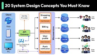
An example of HLD could be an architectural diagram of an e-commerce application showing its main modules like user interface, database, and payment processing.
LLD example may include a pseudocode or flowchart that describes the logic of user authentication.
Memory Aids
Interactive tools to help you remember key concepts
Rhymes
In design, we outline and find, HLD is the map, with LLD the bind.
Stories
Imagine you're an architect planning a house. HLD is like the blueprint showing room layout, while LLD details how each room connects with light switches and furniture placement.
Memory Tools
Remember 'HLD' as 'Headers and Layouts Defined', and LLD as 'Logic and Links Detailed'.
Acronyms
Use 'MAL' to remember HLD components
Modules
Architecture
Links.
Flash Cards
Glossary
- HighLevel Design (HLD)
A design phase that outlines the architecture, modules, and data flow of a system.
- LowLevel Design (LLD)
A design phase that specifies internal logic, algorithms, and interfaces of software components.
- UML Diagrams
Unified Modeling Language diagrams that represent the system architecture and its components.
- ER Diagrams
Entity-Relationship diagrams used to illustrate data relationships.
- Database Schemas
Structured representation of the database design.
Reference links
Supplementary resources to enhance your learning experience.