
Frequency Response of Common Emitter Amplifier
Enroll to start learning
You’ve not yet enrolled in this course. Please enroll for free to listen to audio lessons, classroom podcasts and take practice test.
Interactive Audio Lesson
Listen to a student-teacher conversation explaining the topic in a relatable way.
Introduction to the Common Emitter Amplifier Circuit
🔒 Unlock Audio Lesson
Sign up and enroll to listen to this audio lesson

Today, we are diving into the common emitter amplifier and how it behaves across different frequencies. Can anyone tell me what the main components of this circuit are?

It includes transistors, resistors, and capacitors, right?
Exactly! The transistors amplify the signal while capacitors help filter AC from DC. So, let's remember: *Transistors Amplify and Capacitors Filter* – how's that for a memory aid?

What role does the capacitor play at the output?
Good question! The output capacitor blocks DC voltage, allowing only the amplified AC signal to pass to the next stage. So in this sense, it acts like a gatekeeper for the AC signal.
Understanding Small Signal Models
🔒 Unlock Audio Lesson
Sign up and enroll to listen to this audio lesson

Now that we understand the basic structure, let’s talk about small signal models. What do you think happens to the transistor in this model?

Doesn't it get represented as a dependent current source?
Correct! Specifically, it is modeled as a current source based on the gate-source voltage multiplied by transconductance, g_m. It helps simplify the calculations we need to make.

So, it means we can analyze the frequency response easier?
Precisely! By using these models, we can derive important parameters like gain and cutoff frequencies effectively!
Impact of Circuit Parameters on Frequency Response
🔒 Unlock Audio Lesson
Sign up and enroll to listen to this audio lesson
Let’s dig into how these circuit parameters affect the frequency response. Can anyone share how a resistor or a capacitor might influence cutoff frequency?
I think the values of resistors and capacitors determine whether the circuit acts as a low-pass or high-pass filter?
Exactly! The combination of capacitive and resistive components defines the cutoff frequencies. For instance, the lower cutoff frequency comes from certain capacitors and resistances that form a high-pass filter.
And the upper cutoff frequency relates to series capacitance and resistance interactions?
Right again! This knowledge allows us to optimize the amplifier’s performance over desired frequency ranges.
Bode Plot and Phase Response
🔒 Unlock Audio Lesson
Sign up and enroll to listen to this audio lesson
Now, how do we represent frequency response? One tool we often use is the Bode plot. Who can explain what we plot on this graph?
We plot gain in dB against frequency on a logarithmic scale, right?
Exactly! And the phase shift can also be plotted, revealing how phase changes through cutoff frequencies. Remember: *Gain to dB, Phase to Degrees!*
And those shifts occur at specific frequencies, marking where the amplifier transitions?
Spot on! Understanding these transitions key for designing circuits that perform under various conditions.
Design Considerations for Common Emitter Amplifiers
🔒 Unlock Audio Lesson
Sign up and enroll to listen to this audio lesson
To wrap things up, let's discuss some design considerations. What factors should we consider when designing a common emitter amplifier?
The values of resistors and capacitors for cutoffs!
Yes! Proper selection can ensure our amplifier has the desired gain and behaves predictably across frequency ranges. Keep in mind: *Select Components Wisely for Sound Design!*
And how will we make adjustments if needed in future designs?
Modifications to values can shift frequencies and gain. It’s an iterative design process based on performance testing.
Introduction & Overview
Read summaries of the section's main ideas at different levels of detail.
Quick Overview
Standard
This section discusses the frequency response of common emitter amplifiers, introducing key concepts such as small signal models, Thevenin equivalents, and the impact of capacitive and resistive components on gain and cutoff frequencies. The transformations of the circuit into unified models are explained, enhancing the understanding of amplifier behavior in frequency response.
Detailed
Frequency Response of Common Emitter Amplifier
In this section, we explore the frequency response characteristics of common emitter amplifiers, which are pivotal in analog electronic circuits. The common emitter amplifier's analysis is approached through equivalent circuit models, specifically using small signal models to understand the interactions between various circuit elements.
Circuit Configuration
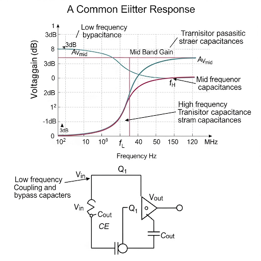
The discussion begins with the representation of the common emitter amplifier circuit, recognizing elements such as capacitors and resistors. The input signal is fed through a coupling capacitor that isolates AC signals from DC levels. At the output, the DC components are blocked by another capacitor, allowing only the amplified AC signal to pass to the next stage.
Small Signal Equivalent Circuit
A notable aspect of this analysis is the conversion of the transistor into its small signal model, characterized by a dependent current source defined by the transconductance parameter (g_m) multiplied by the gate-source voltage (V_gs). The small signal circuit allows for easier calculations of the overall gain. After summarizing the AC equivalent circuits, we derive the Thevenin equivalent for both the input and output ports, revealing the resistances influencing the amplifier.
Cutoff Frequencies and Gain
The frequency response is divided into upper and lower cutoff frequencies, defined by the input and output components of CR and RC circuits, respectively. The lower cutoff frequency primarily arises from the capacitive input network, while the upper cutoff frequency is influenced by the output network characteristics. Understanding these frequencies is crucial for designing amplifiers that behave predictably over a range of frequencies, particularly in signal processing applications.
Bode Plot and Phase Response
In addition, the section discusses how to derive and interpret the Bode plot for gain and phase response, illustrating how these characteristics change across frequencies. For example, the gain in decibels (dB) is connected to the logarithmic frequency scale, where the mid-frequency gain is predominantly determined by the model's transconductance and load resistance. The phase response is discussed in terms of its ramping behavior through corner frequencies, demonstrating how amplifiers adjust their output relative to the input signal characteristics.
Overall, this section provides a comprehensive view of how common emitter amplifiers exhibit frequency response through circuit transformations, leading to important design insights in analog electronics.
Youtube Videos

Audio Book
Dive deep into the subject with an immersive audiobook experience.
Common Emitter Amplifier Overview
Chapter 1 of 5
🔒 Unlock Audio Chapter
Sign up and enroll to access the full audio experience
Chapter Content
So, welcome back after the short break. And we are talking about Frequency Response of the Amplifier and we have seen that generalized form of a network consists of C-R circuit and R-C circuit and in between we do have an amplifier.
Detailed Explanation
In this chunk, the lecturer introduces the topic of frequency response as it relates to amplifiers. The common emitter amplifier is a type of electronic amplifier that uses a transistor to amplify an input signal. It is part of a larger network that includes both capacitors and resistors, forming C-R and R-C circuits inside it.
Examples & Analogies
Think of the common emitter amplifier like a megaphone. Just as a megaphone amplifies your voice to make it heard over a distance, the common emitter amplifier enhances weak electronic signals so they can be utilized in other electronic devices. The C-R and R-C circuits help shape how this amplification affects different frequencies of sound, much like how a megaphone can emphasize certain tones.
Small Signal Equivalent Circuit
Chapter 2 of 5
🔒 Unlock Audio Chapter
Sign up and enroll to access the full audio experience
Chapter Content
If we draw the small signal equivalent circuit after obtaining the quiescent point and other things are defined by R, R; then, Vdd and R.
Detailed Explanation
Here, the lecturer refers to the small signal equivalent model of the common emitter amplifier, which simplifies the analysis of how the amplifier behaves with small changes in input signals. The quiescent point is the DC operating point of the amplifier. The equivalent circuit uses resistors and Vdd (the supply voltage) to illustrate how the amplifier will respond to an AC signal.
Examples & Analogies
Consider tuning a guitar string; when you gently pluck it, the vibrations (small signals) create sound waves. The small signal equivalent circuit represents how, even with a tiny pluck (small signal), the response of the guitar (amplifier) creates a loud tone (output). In essence, it helps us visualize how small inputs lead to amplified outputs.
Thevenin Equivalent and Amplifier Gain
Chapter 3 of 5
🔒 Unlock Audio Chapter
Sign up and enroll to access the full audio experience
Chapter Content
Note that still this is not on equivalent, but it can be easily converted into Thevenin equivalent, namely we can make the amplifier which is having a gain of ‒ g × R.
Detailed Explanation
This section explains how the circuit can be transformed into a Thevenin equivalent circuit to simplify calculations. The gain of the amplifier (which determines how much it amplifies the signal) is given by the product of the transconductance (g) and the resistor (R), indicating a negative sign, which is typical of an inverting amplifier.
Examples & Analogies
Imagine you are cooking a dish and you need to adjust the recipe depending on how many people you are serving. The ingredients (resistor values, in this case) directly affect how tasty (gain) the dish turns out. Just as you might have to multiply quantities to serve a crowd, the gain is a reflection of how much the signal is amplified based on the characteristics of the circuit.
Contribution of Cutoff Frequencies
Chapter 4 of 5
🔒 Unlock Audio Chapter
Sign up and enroll to access the full audio experience
Chapter Content
So, now as I said that we do have C-R circuit, we do have this is the amplifier part and then, we do have the R-C circuit. And from that directly we can say that who are the contributors of the cutoff frequency and the gain.
Detailed Explanation
In this portion, the lecturer discusses how the frequency response can be analyzed by looking at the C-R circuit and R-C circuit contributions. Each circuit type affects the cutoff frequency—the frequency where the gain starts to drop off. The C-R circuit provides a lower cutoff frequency for high-pass filtering, while the R-C circuit provides an upper cutoff frequency for low-pass filtering.
Examples & Analogies
Imagine you are setting up a music playlist and want to create two sections: one for upbeat songs (high-pass filter) and another for slow ballads (low-pass filter). The C-R circuit sets a threshold to filter out slower songs (low frequencies), while the R-C circuit allows only the slow songs to come through, making sure the playlist meets your mood.
Bode Plot and Frequency Response
Chapter 5 of 5
🔒 Unlock Audio Chapter
Sign up and enroll to access the full audio experience
Chapter Content
Now, if you are asked to draw the frequency response or the bode plot particularly the gain plot, I think you will be able to do it yourself.
Detailed Explanation
The Bode Plot is a graphical representation showing how the gain of the amplifier varies with frequency. This is essential for understanding how the amplifier performs across different frequencies. Different sections of the plot will indicate where gain is present and where it drops off, helping to visualize the amplifier's behavior.
Examples & Analogies
Think of the Bode Plot as the visual representation of a roller coaster ride. Just as you can see which portions of the ride are steep (high gain) and which are gentle slopes (low gain), the Bode Plot shows you how well the amplifier works at various frequencies, making it easier to decide where to place it in an audio system.
Key Concepts
-
Frequency Response: The variation of amplifier gain and phase shift concerning frequency changes.
-
Capacitive Input: Capacitors in the input stage influence the low cutoff frequency.
-
Small Signal Analysis: Simplifies the analysis of circuits by using linear models around operating points.
-
Thevenin Equivalent: A method to simplify electrical circuits into a single voltage source and a resistor.
Examples & Applications
If a common emitter amplifier has a coupling capacitor of 10 µF and an input resistance of 1 kΩ, the lower cutoff frequency can be calculated using the formula f_c = 1/(2πRC).
In a circuit where a common emitter amplifier has R_C = 4.7 kΩ and C_L = 100 nF, the upper cutoff frequency would help in determining how fast it can respond to changes in the input signal.
Memory Aids
Interactive tools to help you remember key concepts
Rhymes
In the circuit, signals flow, Capacitors help, that we know!
Stories
Once there was an amplifier connecting signals through capacitors, like a bridge over a river, filtering the noise and only allowing the music to pass through. The transistors stood strong, amplifying the sweet sound across the circuit!
Memory Tools
CRaT - Capacitors Reshape the Amplifier's Transmissions.
Acronyms
C.A.G.E - Capacitors Amplify Gain Effectively.
Flash Cards
Glossary
- Common Emitter Amplifier
A type of amplifier configuration that provides voltage amplification and is characterized by its high gain and phase shift.
- Small Signal Model
An approximation that represents the behavior of nonlinear devices as linear around a specific operating point.
- Transconductance (g_m)
The parameter that defines the relationship between the input voltage and output current in a transistor.
- Gain
The ratio of output signal to input signal, often expressed in decibels (dB).
- Cutoff Frequency
The frequency point at which the output signal power drops to half of its maximum, marking the boundaries of a filter's passband.
- Bode Plot
A graphical representation of a system's transfer function, showing the gain and phase shift as functions of frequency.
Reference links
Supplementary resources to enhance your learning experience.