
Frequency Response of the Amplifier
Enroll to start learning
You’ve not yet enrolled in this course. Please enroll for free to listen to audio lessons, classroom podcasts and take practice test.
Interactive Audio Lesson
Listen to a student-teacher conversation explaining the topic in a relatable way.
Overview of Frequency Response
🔒 Unlock Audio Lesson
Sign up and enroll to listen to this audio lesson

Welcome class! Today, we're diving into the frequency response of amplifiers. To start, can someone explain what we mean by frequency response?

Isn't it how an amplifier reacts to different frequencies of input signals?
Exactly! Frequency response describes how the output of an amplifier varies with frequency. We can visualize this with Bode plots. Now, what are the components that primarily affect this response?

I think capacitors and resistors play a big role in this.
Correct! Capacitors create high-pass or low-pass filter characteristics, while resistors affect the gain and impedance. Let's explore how this works in the context of the Common Source and Common Emitter amplifiers.
Small Signal Models
🔒 Unlock Audio Lesson
Sign up and enroll to listen to this audio lesson

When analyzing our amplifiers, we simplify the complex transistor circuit into a small signal model. Who remembers what this model consists of?

It replaces the transistor with a dependent current source and includes resistors for biasing and loading.
Right! In the CS configuration, we denote the output current based on transconductance. What about the CE configuration?

In the CE model, we also have a voltage-dependent source, right?
Yes, it’s important to visualize these models when plotting frequency responses.
Calculating Gain and Cutoff Frequencies
🔒 Unlock Audio Lesson
Sign up and enroll to listen to this audio lesson
Moving on, the gain of an amplifier is a significant aspect of its frequency response. How do we calculate this in terms of our components?
We calculate gain using transconductance multiplied by the load resistance!
Exactly! And remember that the gain may also be affected by the cutoff frequencies dictated by our C-R and R-C circuits. Can anyone tell me what determines the lower cutoff frequency?
It’s determined by the capacitor and resistor on the input side.
Correct! And for the upper cutoff frequency, which components do we consider?
Those are determined by the output resistors and capacitors.
Great job! Understanding these relationships is key for designing effective amplifiers.
Understanding Bode Plots
🔒 Unlock Audio Lesson
Sign up and enroll to listen to this audio lesson
Now that we have our gain and cutoff frequencies, let's consider how we plot this information. Who can explain what a Bode plot is?
It’s a graph that shows gain and phase versus frequency on a logarithmic scale.
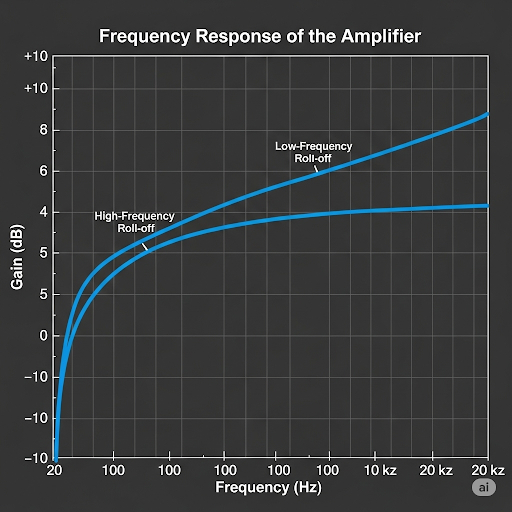
Correct! The x-axis shows frequency while the y-axis typically has gain in decibels and phase in degrees. Can anyone describe what we expect to see in a typical frequency response graph?
We’d see a flat region at mid frequencies, and then drops off near the cutoff frequencies, right?
Exactly! Plotting these responses helps us understand amplifier behavior across a range of input frequencies.
Final Topics & Summary
🔒 Unlock Audio Lesson
Sign up and enroll to listen to this audio lesson
To wrap up, let's summarize how the frequency response allows us to evaluate amplifiers. Why is this important for a designer?
Because it informs us which frequencies the amplifier works best and how to select components!
And it helps us avoid distortion at certain frequencies.
Correct! Understanding frequency response is key to creating effective analog designs. Always remember the interplay between components and their impact on overall performance.
Introduction & Overview
Read summaries of the section's main ideas at different levels of detail.
Quick Overview
Standard
The section delves into the frequency response characteristics of amplifiers, focusing specifically on the Common Source and Common Emitter configurations. It explains the role of capacitors and resistors, discusses the Thevenin equivalents, and relates cutoff frequencies to amplifier gain. Additionally, it provides insight into visualizing frequency response through bode plots.
Detailed
Frequency Response of the Amplifier
The frequency response of amplifiers is critical for understanding how they behave at different frequencies. In this section, we explore both Common Source (CS) and Common Emitter (CE) amplifiers, examining how their components affect performance.
Key Points Covered:
- Circuit Representation: Both CS and CE amplifiers utilize capacitors and resistors, organized into C-R and R-C circuits.
- Small Signal Models: The small signal equivalent for each circuit allows for analyzing how input signals are processed, typically replacing transistors with their small signal models.
- Thevenin Equivalents: For simplicity, the output can be represented using Thevenin equivalents, aiding in understanding gain and frequency behaviors.
- Frequency Response: The cutoff frequencies are determined by the configurations of various capacitors and resistors. The amplifier's response can be visualized using Bode plots, showcasing both gain and phase shift across frequencies.
- Gain Calculations: The gain of the amplifier, denoted as A and typically defined by transconductance, affects the performance near cutoff frequencies and informs design requirements for coupling capacitors.
By the end of this section, students will be equipped with the knowledge to draw frequency response plots and understand how different components in amplifiers influence their overall performance in analog electronic circuits.
Youtube Videos

Audio Book
Dive deep into the subject with an immersive audiobook experience.
Overview of Amplifier Frequency Response
Chapter 1 of 6
🔒 Unlock Audio Chapter
Sign up and enroll to access the full audio experience
Chapter Content
So, welcome back after the short break. And we are talking about Frequency Response of the Amplifier and we have seen that generalized form of a network consists of C-R circuit and R-C circuit and in between we do have an amplifier. Now, let we try to map that model or rather actual circuit mapping to that unified model.
Detailed Explanation
This chunk introduces the concept of frequency response in amplifiers and how it is structured. The speaker explains that amplifiers can be represented as networks including capacitive-resistive (C-R) and resistive-capacitive (R-C) circuits, emphasizing the importance of understanding their interaction to map to a unified model.
Examples & Analogies
Think of an amplifier's frequency response like a music equalizer. Just as different frequencies of sound can be tuned and adjusted using various controls, amplifiers adjust and respond to different frequencies in an electrical signal.
Common Source Amplifier Circuit Perspective
Chapter 2 of 6
🔒 Unlock Audio Chapter
Sign up and enroll to access the full audio experience
Chapter Content
So, say to start with we do have common source amplifier and the circuit is given here. The circuit is given here for your reference and if you see here we do have the main part main amplifier here and then, we are feeding the signal through this capacitor called say C.
Detailed Explanation
This section describes the specific setup of a common source amplifier. It notes that the main amplifier accepts input signals through a coupling capacitor, which blocks DC components, allowing only AC signals to pass. This is essential for analyzing the amplifier's frequency response.
Examples & Analogies
Imagine this capacitor as a selective gatekeeper. Just like a person who only lets certain guests into a party, the capacitor allows certain frequency signals to pass through while blocking unwanted DC, maintaining the amplifier's focus on AC signals.
Small Signal Equivalent Circuit
Chapter 3 of 6
🔒 Unlock Audio Chapter
Sign up and enroll to access the full audio experience
Chapter Content
Now, if we draw the small signal equivalent circuit after obtaining the quiescent point and other things are defined by R , R ; then, V and R. What we obtained in our previous discussion we say that at the middle, at the middle we got the main amplifier circuit.
Detailed Explanation
In this chunk, the speaker shifts to constructing the small signal equivalent circuit of the amplifier, which simplifies analysis by replacing the transistor with a small signal model. It emphasizes the importance of identifying resistances and voltages (like V and R values) to understand how the amplifier will respond to small fluctuations in signal.
Examples & Analogies
Think of the small signal equivalent circuit like creating a miniature model of a building. The model helps you see how spaces work within the large structure, just as simplifying the amplifier's components helps analyze its functionality under small signal conditions.
Thevenin Equivalent Conversion
Chapter 4 of 6
🔒 Unlock Audio Chapter
Sign up and enroll to access the full audio experience
Chapter Content
So, this part the output port part, it can be translated into Thevenin equivalent, namely we can make the amplifier which is having a gain of ‒ g × R.
Detailed Explanation
The Thevenin equivalent allows the output circuit to be simplified into a simpler form with a single voltage source and a single resistance, making it easier to analyze how the amplifier behaves under different loading conditions. The gain is expressed as negative, indicating phase inversion, common in amplifiers.
Examples & Analogies
Just like converting a complicated recipe into a simpler version with fewer steps makes cooking more straightforward, using Thevenin's theorem simplifies our understanding of the amplifier's output, allowing us to quickly assess its performance.
Cutoff Frequency and Gain Contributions
Chapter 5 of 6
🔒 Unlock Audio Chapter
Sign up and enroll to access the full audio experience
Chapter Content
So, now as I said that we do have C-R circuit, we do have this is the amplifier part and then, we do have the R-C circuit. And from that directly we can say that who are the contributors of the cutoff frequency and the gain.
Detailed Explanation
This segment explains how different parts of the circuit contribute to the overall frequency response of the amplifier, specifically focusing on the cutoff frequencies established by C-R and R-C components. Understanding these contributions is key to predicting how the amplifier will behave at different frequencies.
Examples & Analogies
Think of the amplifier like a ski slope, where the C-R and R-C parts are like different sections of the slope affecting a skier's speed and control. Some sections may be steep (contributing to higher frequencies), while others might be gentler (contributing to lower frequencies), directly influencing the overall experience.
Frequency Response Overview
Chapter 6 of 6
🔒 Unlock Audio Chapter
Sign up and enroll to access the full audio experience
Chapter Content
So, what we have for our reference again, I am just keeping this diagram, we just now have discussed the C-R circuit and R-C aspect in shaping the frequency response of the amplifier.
Detailed Explanation
This overview summarizes how the amplifiers are influenced by their RC configurations and how they result in particular frequency responses. It clarifies that the interactions between these circuits define the corners of the amplifier's operational frequency range, which helps in determining band limits.
Examples & Analogies
Consider cooking a dish with various spices. Each spice affects the flavor; similarly, the C-R and R-C circuits influence the amplifier’s frequency response, shaping the final 'sound' or output of the signal.
Key Concepts
-
Frequency Response: How an amplifier reacts to various frequencies.
-
Thevenin Equivalent: Simplifying circuits to analyze gain and behavior.
-
Gain: The amplification ratio, key to amplifier performance.
-
Bode Plots: Visual representations of frequency response.
Examples & Applications
In a CS amplifier, using a larger coupling capacitor decreases the lower cutoff frequency, allowing more low-frequency signals to be amplified.
CE amplifiers can have their gain increased by adjusting the load resistor placed at the output.
Memory Aids
Interactive tools to help you remember key concepts
Rhymes
Gain and cutoff, remember this, Amplifiers work, a signal's bliss. C and R in play, frequency's sway, Shapes the output, come what may!
Stories
Imagine building a chocolate fountain. The fountain represents an amplifier ensuring all chocolate flows smoothly. Depending on the size of the pump (gain) and the flow (cutoff frequency), the fountain delivers different chocolate goodness!
Memory Tools
To remember the key components: 'C-AP' - Capacitors Affect Performance: Cutoff frequency impacts gain.
Acronyms
G-C-P (Gain, Cutoff, Phase) - Three essential elements every amplifier designer must know.
Flash Cards
Glossary
- Frequency Response
The output behavior of an amplifier as it relates to varying inputs of different frequencies.
- Common Emitter Amplifier (CE)
An amplifier configuration that uses a transistor where the emitter is common to both input and output.
- Common Source Amplifier (CS)
An amplifier configuration that uses a FET where the source terminal is common for input and output.
- Thevenin Equivalent
A simplification of a complex circuit to a simple voltage source with an equivalent resistance.
- Gain
The ratio of output voltage to input voltage, often expressed in decibels (dB).
- Cutoff Frequency
The frequency at which the output signal begins to significantly attenuate.
- Bode Plot
Graphical representation of a system's frequency response, showing gain and phase versus frequency.
Reference links
Supplementary resources to enhance your learning experience.