
DIMENSIONING, ABBREVATION AND CONVENTIONAL REPRESENTATION AS PER 962
Enroll to start learning
You’ve not yet enrolled in this course. Please enroll for free to listen to audio lessons, classroom podcasts and take practice test.
Interactive Audio Lesson
Listen to a student-teacher conversation explaining the topic in a relatable way.
Importance of Abbreviations
🔒 Unlock Audio Lesson
Sign up and enroll to listen to this audio lesson

Today, we’ll discuss the importance of abbreviations in engineering drawings, especially as it relates to IS: 962 standards.

Why do we need abbreviations in the first place?
Great question! Abbreviations help us to convey complex architectural and engineering terms in a simplified form, ensuring clarity and uniformity in communication.

Does that mean every drawing should use the same abbreviations?
Exactly! Consistent usage prevents confusion, particularly when multiple stakeholders are involved.

So, it saves time too, right?
Absolutely! By using accepted abbreviations, we reduce the need for lengthy explanations.
To remember this, think of the acronym 'CLEAR' — Clarity, Length reduction, Efficiency, Abbreviation, and Recognition!

That's a good mnemonic!
Let’s summarize. Abbreviations enhance clarity, save time, and must be standard across all drawings. Now, any further questions?
Conventional Symbols and Their Usage
🔒 Unlock Audio Lesson
Sign up and enroll to listen to this audio lesson

Next, let’s delve into the use of conventional symbols in our drawings.
What exactly do you mean by conventional symbols?
Conventional symbols represent various building materials and fittings without being drawn to scale, meaning they simplify the representation for quicker identification.
Can you give an example of a conventional symbol?
Sure! For instance, we often use a specific symbol for a water closet or a sink. This representation allows for quick understanding.
Why is that beneficial?
Using symbols saves space on the drawing sheet and facilitates easier reading and understanding.
Remember the idea of 'SIMPLE' — Symbols Indicate Material and Provide Learning Ease!
I see how that works!
Great! So, how do conventional symbols help in project execution?
Dimensioning Techniques
🔒 Unlock Audio Lesson
Sign up and enroll to listen to this audio lesson
Let’s now turn our attention to dimensioning techniques, which are essential for conveying accurate sizes in drawings.
What does dimensioning involve?
Dimensioning involves annotating lengths, widths, and heights to ensure everyone involved in the project understands the intended sizes.
Are there different methods to dimension a drawing?
Yes! You can dimension using linear measures or angular measures, depending on what’s most appropriate for the drawing.
And is it important to follow specific standards for dimensioning?
Absolutely! Following the IS: 962 guidance ensures uniformity and clarity across all technical drawings.
To remember dimensioning essentials, think of 'DIME' — Dimension Indication Must be Explained!
That's very catchy!
In summary, accurate dimensioning facilitates construction accuracy and efficiency while ensuring everyone is on the same page.
Introduction & Overview
Read summaries of the section's main ideas at different levels of detail.
Quick Overview
Standard
In architectural and engineering drawings, using standardized abbreviations and symbols is crucial to ensure clarity and uniformity. This section outlines the systematic notation for architectural terms and emphasizes the significance of avoiding confusion in drawing interpretations.
Detailed
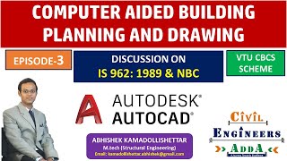
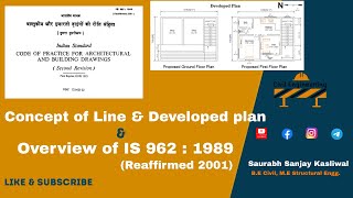
Dimensioning, Abbreviation and Conventional Representation as per 962
In the context of architectural and engineering drawings, abbreviations are essential for achieving clarity and consistency. The Indian Standards Institute (ISI) outlines the necessity of systematic notation for architectural and building terms to avoid confusion and ambiguity. Moreover, the guidelines used in general building drawings help maintain uniformity across various documentation and practical applications in civil engineering. The impact of correct dimensioning and representation is significant as it ensures clear communication among architects, engineers, and construction personnel. Thus, adherence to abbreviations and symbols helps streamline the understanding of drawings, which is vital for successful project execution. This standardization is not just about aesthetics; it also plays a crucial role in the efficiency of interpretation and implementation on construction sites.
Youtube Videos


Audio Book
Dive deep into the subject with an immersive audiobook experience.
Importance of Abbreviations
Chapter 1 of 4
🔒 Unlock Audio Chapter
Sign up and enroll to access the full audio experience
Chapter Content
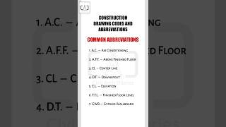
Abbreviations are generally used in drawing for the sake of clarity. A systematic notation of architectural and building terms is necessary for uniformity, and for avoiding confusion and ambiguity.
Detailed Explanation
Abbreviations in technical drawings serve a crucial purpose: they help convey information clearly and succinctly. By standardizing how architectural and building terms are abbreviated, we reduce the chances of misinterpretation and confusion, especially when different people are involved in reading and using these drawings. It’s essential that these abbreviations remain consistent in both singular and plural forms to maintain clarity.
Examples & Analogies
Consider how in everyday life we use abbreviations like 'ASAP' for 'as soon as possible'. This kind of shorthand makes communication quicker and clearer, especially in fast-paced environments like busy workplaces. Similarly, in architectural drawings, using consistent abbreviations helps everyone understand the plans more rapidly and reduces errors.
Recommendation of Abbreviations and Symbols
Chapter 2 of 4
🔒 Unlock Audio Chapter
Sign up and enroll to access the full audio experience
Chapter Content
Abbreviations and symbols are recommended for use in general building drawings.
Detailed Explanation
The use of abbreviations and symbols in building drawings is not just a preference but a recommendation by industry standards. These symbols and abbreviations are designed to encapsulate complex ideas into easily recognizable forms, which saves space on the drawing and allows for quicker communication. This uniform approach means that anyone accustomed to these symbols can interpret the drawings quickly and accurately, regardless of their background.
Examples & Analogies
Think of highway signs, which use symbols and abbreviated text to convey important information quickly, such as '30 MPH' to indicate speed limits. Just as drivers need to decode these signs instantly, engineers and architects need to interpret drawings that use standard abbreviations and symbols for efficiency and effectiveness.
Starting AutoCAD
Chapter 3 of 4
🔒 Unlock Audio Chapter
Sign up and enroll to access the full audio experience
Chapter Content
We can start on Auto CAD session by double clicking the left mouse button on an Auto CAD icon or by clicking the start button choosing the program click on Auto CAD. Auto CAD opens loads the menu and display the start up dialogue box.
Detailed Explanation
To begin using AutoCAD, you initiate the software by either double-clicking its icon or navigating through the start menu. Once opened, AutoCAD displays its main menu and a start-up dialogue box that allows users to create a new drawing or open existing ones. This straightforward process is designed to get users ready to create drawings efficiently.
Examples & Analogies
Starting AutoCAD is similar to booting up a computer or opening any software application on your device. Just like you would click an icon to start a program you use frequently, in the same manner, you access AutoCAD, ready to begin your design work.
Components of the AutoCAD Editor Screen
Chapter 4 of 4
🔒 Unlock Audio Chapter
Sign up and enroll to access the full audio experience
Chapter Content
Components of AUTO CAD editor screen: Drawing Area: Center of Screen which is used for creating the drawing. Command Lines: We can type command and execute it. Menu Bar: Menu bar displays the basic command along with submenu to occur the general control and setting for the efficient handling of tools.
Detailed Explanation
The AutoCAD editor screen consists of several key components essential for creating drawings. The drawing area is the main workspace where the designs are made. The command line is where users can type specific commands, providing precise control over the functions of the software. The menu bar contains various commands and tools, allowing for efficient navigation and operation. Understanding each of these components is vital for effective use of AutoCAD.
Examples & Analogies
Using AutoCAD is like using a desktop publishing application. Just as a word processor has a text area, toolbars, and menus for formatting documents, AutoCAD provides a similar structure but tailored for technical drawing, enabling users to construct detailed architectural designs methodically.
Key Concepts
-
Abbreviations enhance clarity and reduce lengthiness in drawings.
-
Conventional symbols aid quick identification of building components.
-
Dimensioning is vital for communicating accurate measurements.
-
Standardization increases uniformity and efficiency in technical drawings.
Examples & Applications
Using 'WC' as an abbreviation for 'Water Closet' in architectural plans.
Representing a sink with a specific symbol that signifies its location on the drawing.
Memory Aids
Interactive tools to help you remember key concepts
Rhymes
When building plans come into sight, abbreviations make it right!
Stories
Once upon a time, in a busy city, architects used secret codes to communicate. These codes were their abbreviations and symbols, which made their plans easy to read and understand at construction sites.
Memory Tools
Remember 'BASIC': Building Abbreviations Save Interpretation Confusion.
Acronyms
Use 'DASH' for Drawing Accuracy, Symbols, and Height!
Flash Cards
Glossary
- Abbreviation
A shortened form of a word or phrase to enhance clarity in technical drawings.
- Conventional Symbol
A symbol used to represent a material or component in drawings, aiding in quick identification.
- Dimensioning
The process of indicating measurements on a drawing to convey size accurately.
- Standardization
The implementation of standards to ensure consistency and uniformity in documentation.
Reference links
Supplementary resources to enhance your learning experience.