
INTRODUCTION
Enroll to start learning
You’ve not yet enrolled in this course. Please enroll for free to listen to audio lessons, classroom podcasts and take practice test.
Interactive Audio Lesson
Listen to a student-teacher conversation explaining the topic in a relatable way.
Introduction to Working Drawings
🔒 Unlock Audio Lesson
Sign up and enroll to listen to this audio lesson

Today, we'll delve into working drawings, which are essential in civil engineering. Can anyone tell me what they think a working drawing is?

I think it's a drawing that shows how to build something?
Exactly! A working drawing is a representation that provides key details like size, shape, and the materials to be used. It helps visualize the project before it begins.

So, it's like a blueprint for construction?
That's right, and in the construction process, following these drawings ensures everything is built correctly. Remember, we often refer to them as the blueprint of the project!

Are there standards we need to follow for these drawings?
Good question! Yes, the **Indian Standards IS: 962** guide us on what sizes and layouts to use. Codes help maintain consistency across projects.

So, what has changed with technology in making these drawings?
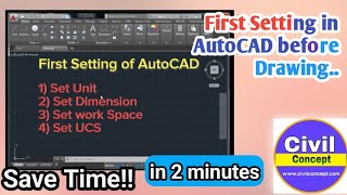
Great point! Traditional methods relied heavily on individual skill, but now we use tools like **AutoCAD** for drafting, which enhances accuracy and speed.
To summarize, working drawings are crucial for the visual representation of structures, follow specific standards, and have greatly evolved with technology.
Paper Sizes and Layouts
🔒 Unlock Audio Lesson
Sign up and enroll to listen to this audio lesson

Let's discuss the different sizes of drawing sheets we use in engineering. Can someone name a size of paper we may use for drawings?
Is A3 one of them?
Exactly! We often work with various sizes like A0, A1, A2, A3, and A4 for different scales of drawings. A0 is quite large, isn't it?
Why do we need different sizes?
Different project scopes require different levels of detail. Larger sheets allow for extensive plans, whereas smaller sheets suffice for minor details.
What about the layout? Is there a specific way we should present our drawings?
Absolutely! Each drawing should have a border with a standard margin. This keeps our work neat and readable. Who can tell me what important information goes into the title block?
It should have the title, organization name, and scale, right?
Perfect! Remember, the title block standardizes how we present information, making it clear and professional.
To recap, different sizes of sheets accommodate various project needs, and adhering to layout standards is crucial for clarity.
The Importance of Scales in Drawings
🔒 Unlock Audio Lesson
Sign up and enroll to listen to this audio lesson
Let's now talk about scales in drawings. Why do you think we use scales instead of drawing everything to actual size?
Because buildings can be really large?
Exactly! Many structures cannot fit on a single sheet at full size. Scaling allows us to represent large structures in a manageable format.
What are some typical scales we might use?
We use different scales for various purposes: 1:200 for large plot plans, 1:50 for floor plans, and detailed drawings can be at 1:20 or even 1:10.
How does this help builders?
It allows them to visualize the size and dimensions of the building, making it easier to plan. Think of it like using a map to find your way.
To wrap up, scales are essential in displaying the right dimensions that relate to actual building sizes, aiding both design and construction.
Introduction & Overview
Read summaries of the section's main ideas at different levels of detail.
Quick Overview
Standard
This section introduces the concept of working drawings essential for civil engineering projects, defining their purpose in conveying structural details. It also discusses key standards for engineering drawings and the shift from manual drafting to Computer Aided Design (CAD) systems like AutoCAD.
Detailed
Detailed Summary
The introduction outlines the foundational aspects of working drawings, which are crucial in civil engineering for accurately representing technical structures. Working drawings convey vital details including shape, size, materials, and location, providing a comprehensive view of the structure prior to its construction. This is essential in civil engineering projects, where precision and adherence to standards are paramount.
The practices followed in building drawing offices adhere to specific codes as detailed in Indian Standards IS: 962 and IS: 10711, which dictate aspects such as paper sizes, drawing layouts, lettering sizes, and the use of graphical symbols. It highlights the transition from traditional manual drawing methods, reliant on individual precision, to modern Computer Aided Design (CAD) tools like AutoCAD, which facilitate quicker and more accurate drafting. Overall, this section establishes the framework within which effective building planning and drawing is executed.
Youtube Videos


Audio Book
Dive deep into the subject with an immersive audiobook experience.
Definition of Working Drawing
Chapter 1 of 6
🔒 Unlock Audio Chapter
Sign up and enroll to access the full audio experience
Chapter Content
The art of representing technical structures with the aid of drawing instruments on paper is known as working drawing.
Detailed Explanation
A working drawing is a precise and accurate representation of a technical structure, created using various drawing instruments. It serves as a blueprint, guiding the construction process. By employing specific drawing techniques and tools, the working drawing articulates details such as dimensions, materials, and overall design.
Examples & Analogies
Think of a working drawing like a recipe in a cookbook. Just as a recipe provides instructions on how to prepare a meal, including ingredients and cooking time, a working drawing gives detailed information on how to construct a building or structure.
Importance of Working Drawings
Chapter 2 of 6
🔒 Unlock Audio Chapter
Sign up and enroll to access the full audio experience
Chapter Content
A working drawing if properly drawn can convey the details such as shape, size, materials used, location, placing and planning of different services; in short, it conveys the whole form of the structure on the paper before the materialization of the structure.
Detailed Explanation
Working drawings are crucial because they communicate all necessary details about a project before actual construction begins. They include the design, specifications, and arrangements of various elements involved in the project, ensuring that everyone understands what the final structure will look like and how it will function.
Examples & Analogies
Imagine that you are an artist creating a large mural. Before starting, you would sketch your design on paper to determine how each element fits together. Similarly, a working drawing allows architects and engineers to visualize and organize their construction plans before they start building.
Construction Projects and Working Drawings
Chapter 3 of 6
🔒 Unlock Audio Chapter
Sign up and enroll to access the full audio experience
Chapter Content
So these drawings are the most prior thing in any civil engineering projects.
Detailed Explanation
In civil engineering, working drawings are a priority because they set the foundation for all further activities in a project. These detailed documents guide construction workers, engineers, and project managers, ensuring that everyone is on the same page and understands how the project will unfold.
Examples & Analogies
Consider a construction project like assembling a complex puzzle. Each piece of the puzzle is designed to fit perfectly with others. Without the box lid showing the complete image (similar to a working drawing), it would be challenging to know how to put the pieces together correctly.
Code of Practice for Drawings
Chapter 4 of 6
🔒 Unlock Audio Chapter
Sign up and enroll to access the full audio experience
Chapter Content
The building drawing office practices followed are based on certain basic principles as laid down by ISI. These principles are called 'Code of Practice' and the guidelines for engineering drawing are as per IS: 962- 'Code of Practice for Architectural and Building drawings' and IS: 10711.
Detailed Explanation
Every engineering discipline has standards and guidelines that shape how drawings are prepared and depicted. The 'Code of Practice' provides these essential guidelines, helping to standardize the way information is conveyed in drawings. It encompasses various aspects such as the size of papers, layouts, representations, and much more.
Examples & Analogies
Think of the 'Code of Practice' as a set of rules for a game. Just as players must follow the rules to ensure fair play and consistent outcomes, architects and engineers use these codes to create drawings that are reliable and universally understood.
Transition to Computer Aided Design
Chapter 5 of 6
🔒 Unlock Audio Chapter
Sign up and enroll to access the full audio experience
Chapter Content
An engineering drawing traditionally is prepared using drawing instruments but the accuracy of this drawing is dependent on the individual skill of the person drawing them. The modifications and repetition work of this drawing are cumbersome and time consuming.
Detailed Explanation
Traditionally, engineers and architects would create drawings by hand using tools like rulers and compasses. However, the level of precision and the ease of making changes depended heavily on the skill of the individual. This process can be tedious and prone to errors, leading to inefficiencies in the design process.
Examples & Analogies
It's like writing a letter by hand. If you make a mistake, you have to start over, which can be frustrating. In contrast, using a word processor allows for easy edits and adjustments, making the overall process smoother and faster.
Introduction to Computer Aided Design
Chapter 6 of 6
🔒 Unlock Audio Chapter
Sign up and enroll to access the full audio experience
Chapter Content
Hence the popular alternative for manual preparation of engineering drawing is the Computer Aided Design and Drafting System. One such most widely used drafting tool is AutoCAD.
Detailed Explanation
Computer-Aided Design (CAD) tools like AutoCAD have revolutionized the way engineering drawings are made. These software solutions not only speed up the drawing process but also enhance accuracy, allowing for easy modifications, layering, and complex designs that would be challenging to achieve manually.
Examples & Analogies
Imagine using a 3D modeling program for video games, where you can create detailed environments with precision. Just as game designers can alter elements quickly and easily, architects and engineers use AutoCAD to design and refine their drawings efficiently.
Key Concepts
-
Working Drawings: Essential representations for construction detailing.
-
AutoCAD: A major software tool for drafting in engineering.
-
Standards and Codes: Guidelines ensuring precision in drawings.
Examples & Applications
The use of different paper sizes (A0, A1, A2) in architectural plans.
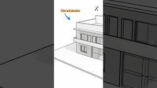
The application of scale in a building drawing to visualize a large structure on a manageable sheet.
Memory Aids
Interactive tools to help you remember key concepts
Rhymes
For working drawings to be just right, scale and detail are in sight.
Stories
Imagine a builder creating a new home. They start with a working drawing, which helps them visualize each room, ensuring everything fits perfectly before construction begins.
Memory Tools
To remember the title block details, say: 'T-N-D-S-S' which stands for Title, Name, Drawing number, Scale, Signature.
Acronyms
W-D for Working Drawings – your blueprint for building success.
Flash Cards
Glossary
- Working Drawing
A detailed drawing that conveys technical information such as shape, size, and materials of a structure before construction.
- AutoCAD
A software application used for computer-aided design and drafting to create accurate 2D and 3D drawings.
- Indian Standards (ISI)
Specifications and guidelines established to maintain quality and consistency in engineering and architectural drawings.
Reference links
Supplementary resources to enhance your learning experience.