
DRAWING BASICS
Enroll to start learning
You’ve not yet enrolled in this course. Please enroll for free to listen to audio lessons, classroom podcasts and take practice test.
Interactive Audio Lesson
Listen to a student-teacher conversation explaining the topic in a relatable way.
Introduction to Working Drawings
🔒 Unlock Audio Lesson
Sign up and enroll to listen to this audio lesson

Welcome class! Today, we're going to talk about the basics of working drawings. These are essential in civil engineering as they represent the technical details of a structure before it's built. Can anyone tell me what a working drawing conveys?

It shows the shape, size, and materials used, right?
Exactly! It conveys all necessary details that support the planning and execution of the project. Now, can someone explain why these drawings are considered a priority in civil engineering projects?

Because they help prevent mistakes and guide construction!
Great point! They are crucial for accuracy and communication in the field. Remember, a well-drawn working drawing saves time and resources.
Sizes of Drawings
🔒 Unlock Audio Lesson
Sign up and enroll to listen to this audio lesson

Let's shift our focus to the standard sizes of drawing sheets. Why do you think it's important to have standard sizes?

It helps to maintain consistency in presentations.
Exactly! Standard sizes ensure that everyone in the field can read and understand the drawings without confusion. The common sizes are A0, A1, A2, A3, and A4. Can anyone recall what the trimmed size of A1 is?

Isn’t it 594 by 841 mm?
Yes! Excellent recall! Knowing these dimensions is essential for preparing drawings correctly.
Layout and Title Block
🔒 Unlock Audio Lesson
Sign up and enroll to listen to this audio lesson
Now, let’s explore the layout of our drawings, especially the title block. What information do we typically find in a title block?
It includes the title of the drawing and the drawing number, right?
And the revisions and scale too!
Correct! A title block needs to be clear and contain all this information for proper documentation. This is vital for version control and identification of the drawing.
Understanding Scales
🔒 Unlock Audio Lesson
Sign up and enroll to listen to this audio lesson
Today we are learning about scales in drawings. What is the purpose of using a scale in engineering drawings?
To represent larger structures in a smaller format.
Exactly! We can use a full scale of 1:1 for smaller objects but must reduce for larger buildings. Can anyone tell me some common scales used for building drawings?
1:100 for small plots and 1:50 for floor plans!
Exactly right! Remember these scaling methods as they are key for clarity.
Introduction & Overview
Read summaries of the section's main ideas at different levels of detail.
Quick Overview
Standard
This section covers the essential concepts of drawing basics in civil engineering, including working drawings, layout and title blocks, scales, and the use of AutoCAD. Understanding these principles is crucial for creating accurate and effective engineering drawings.
Detailed
DRAWING BASICS
The section on 'Drawing Basics' emphasizes the significance of working drawings in civil engineering, which serve as a crucial communication tool representing technical structures. Properly executed drawings convey fundamental details such as dimensions, materials, and services necessary for successful construction projects.
Key Concepts:
- Working Drawings: These detailed representations are essential before any construction and follow guidelines set by ISI standards for size, layout, and symbols.
- Drawing Sizes: Standard sizes for drawing sheets are provided, ensuring uniformity in presentation.
- Layout and Title Block: Every drawing includes specific information such as title, organization name, and revision status, with a structured layout.
- Scales: Utilizing scales allows for the representation of large structures on manageable sheets, with common scales included for various types of plans.
- Line Work, Lettering, and Dimensioning: Emphasizes the quality and uniformity of lines and lettering in technical drawings, which is specified in various standards.
- Conventional Symbols: Identifying materials and components through universally recognized symbols and abbreviations streamlines the interpretation of drawings.
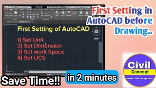
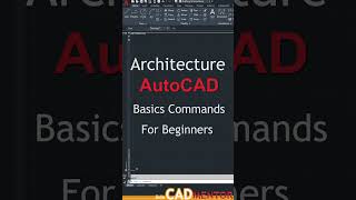
- AutoCAD: Introduces the functionality of AutoCAD for creating and modifying drawings, showing its advantages over traditional drawing methods.
In summary, mastering these drawing basics is essential for anyone involved in civil engineering and construction.
Youtube Videos


Audio Book
Dive deep into the subject with an immersive audiobook experience.
Introduction to Working Drawings
Chapter 1 of 5
🔒 Unlock Audio Chapter
Sign up and enroll to access the full audio experience
Chapter Content
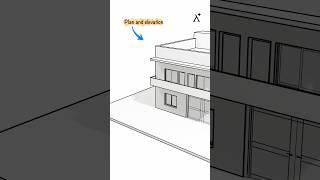
The art of representing technical structures with the aid of drawing instruments on paper is known as working drawing. A working drawing if properly drawn can convey the details such as shape, size, materials used, location, placing and planning of different services; in short, it conveys the whole form of the structure on the paper before the materialization of the structure. So these drawings are the most prior thing in any civil engineering project.
Detailed Explanation
Working drawings are essential documents used in civil engineering to represent technical structures. They are created with specific drawing instruments and provide detailed information about the structure. This includes aspects like the shape, size, materials, and layout of services. Properly prepared working drawings act as a blueprint for construction, ensuring that everyone involved understands what needs to be built before any physical work begins.
Examples & Analogies
Imagine you're creating a recipe for a complicated dish. The recipe outlines each ingredient and step required to prepare it. Similarly, a working drawing acts as a recipe for constructing buildings, detailing everything from materials to spatial arrangements, ensuring that architects and builders follow a clear guideline.
Code of Practice for Engineering Drawings
Chapter 2 of 5
🔒 Unlock Audio Chapter
Sign up and enroll to access the full audio experience
Chapter Content
The building drawing office practices followed are based on certain basic principles as laid down by ISI. These principles are called 'Code of Practice' and the guidelines for engineering drawing are as per IS: 962-'Code of Practice for Architectural and Building drawings' and IS: 10711. They include size of papers, layout of drawings, conventional representations, sizes of letters and numerals on drawings, graphical symbols and abbreviations.
Detailed Explanation
To ensure consistency and clarity in engineering drawings, specific codes of practice are followed, as set by the Indian Standards Institute (ISI). These codes establish rules regarding the sizes of drawing sheets, the format and layout of the drawings, the symbols to be used for various materials, and the standard dimensions for letters and numbers. Adhering to these guidelines helps maintain quality and understanding across various projects.
Examples & Analogies
Think of these guidelines like the rules of a game. Just as a game needs rules to ensure everyone plays in the same way, engineering drawings require standards to ensure that everyone interprets and uses the information correctly. Without these rules, there could be confusion and mistakes in designs.
Importance of Drawing Instruments
Chapter 3 of 5
🔒 Unlock Audio Chapter
Sign up and enroll to access the full audio experience
Chapter Content
An engineering drawing traditionally is prepared using drawing instruments, but the accuracy of this drawing is dependent on the individual skill of the person drawing them. The modifications and repetition work of this drawing are cumbersome and time consuming. Hence the popular alternative for manual preparation of engineering drawing is the Computer Aided Design and Drafting System.
Detailed Explanation
Traditionally, engineering drawings rely on manual skills and drawing instruments, which require a high level of precision. Any errors or needed modifications can be labor-intensive and time-consuming to fix. As a solution, Computer Aided Design (CAD) systems have gained popularity. These digital tools streamline the drawing process, allowing for quick modifications and more precise output, ultimately saving time and improving accuracy.
Examples & Analogies
Imagine drawing a detailed picture by hand, where a single mistake means starting over. Now, think of using digital tools to create that picture, where you can easily erase and adjust parts without affecting the whole. CAD systems for engineering drawings serve this purpose, making design processes more efficient.
Size and Standardization of Drawing Sheets
Chapter 4 of 5
🔒 Unlock Audio Chapter
Sign up and enroll to access the full audio experience
Chapter Content
Drawing sheets are cut from rolls and are made into different sizes so that each size can be worked upon. The table below gives the standard size of drawing sheets.
| Sl.No. Size Designation | Trimmed size of the drawing sheet in mm |
|---|---|
| 1 | A0 |
| 2 | A1 |
| 3 | A2 |
| 4 | A3 |
| 5 | A4 |
Detailed Explanation
Drawing sheets come in standardized sizes, which are crucial for maintaining uniformity across projects. These sizes, like A0, A1, A2, A3, and A4, help determine how much detail can fit on a sheet and ensure consistency across various engineering drawings. Each size serves specific needs, from large architectural designs to smaller detailed schematics.
Examples & Analogies
Think of standardized drawing sizes like different sizes of canvases for artists. Just as an artist chooses the canvas size based on the type of painting, engineers select drawing sizes depending on the complexity and details of the project to ensure clarity and precision.
Layout and Title Block Essentials
Chapter 5 of 5
🔒 Unlock Audio Chapter
Sign up and enroll to access the full audio experience
Chapter Content
Border lines should be drawn all round the drawing sheet leaving a margin of 25 mm or 30 mm on the left-hand side, and 10 mm on all the other sides. Title box is drawn at the right bottom corner of the sheet and remaining space is utilized for drawing. A title block normally carries the following information: (i) Title of the drawing (ii) Name of the organization (iii) Drawing number with revision number (iv) Scale (v) Date of the drawing (vi) Signature of the concerned authorities.
Detailed Explanation
The layout of a drawing sheet is crucial for presenting information clearly. The borderlines and margins help to keep the content organized and visually appealing. The title block, usually placed in a specific corner, contains vital information about the drawing such as its title, organization, drawing number, revision number, scale, date, and signatures. This ensures that anyone reviewing the drawing can quickly grasp essential details without confusion.
Examples & Analogies
Think of the title block like a book cover: it provides important information at a glance. Just as a good book cover lets you know what to expect inside, a well-organized title block informs anyone looking at the drawing about its purpose and authenticity.
Key Concepts
-
Working Drawings: These detailed representations are essential before any construction and follow guidelines set by ISI standards for size, layout, and symbols.
-
Drawing Sizes: Standard sizes for drawing sheets are provided, ensuring uniformity in presentation.
-
Layout and Title Block: Every drawing includes specific information such as title, organization name, and revision status, with a structured layout.
-
Scales: Utilizing scales allows for the representation of large structures on manageable sheets, with common scales included for various types of plans.
-
Line Work, Lettering, and Dimensioning: Emphasizes the quality and uniformity of lines and lettering in technical drawings, which is specified in various standards.
-
Conventional Symbols: Identifying materials and components through universally recognized symbols and abbreviations streamlines the interpretation of drawings.
-
AutoCAD: Introduces the functionality of AutoCAD for creating and modifying drawings, showing its advantages over traditional drawing methods.
-
In summary, mastering these drawing basics is essential for anyone involved in civil engineering and construction.
Examples & Applications
A scale of 1:50 in a floor plan implying that 1 unit on the drawing equals 50 units in reality.
A title block that includes the title of a building, the organization’s name, a drawing number, and the date.
Memory Aids
Interactive tools to help you remember key concepts
Rhymes
To scale and draw with great finesse, use a title block, you must confess.
Stories
Once upon a time, a civil engineer named Sam always kept his drawing sheets organized with proper sizes. He knew that without a scale, his drawings would fail!
Memory Tools
S.T.A.C.: Scale, Title Block, AutoCAD, Conventional Symbols help you remember key drawing elements.
Acronyms
D.R.A.W
Dimensions
Representation
Accuracy
Width - all fundamental in engineering drawings.
Flash Cards
Glossary
- Working Drawing
A detailed representation of a structure, including dimensions, materials, and placements.
- Scale
A ratio that represents the relationship between a drawing's dimensions and the actual dimensions of the object.
- Title Block
A bordered section on a drawing sheet containing essential information about the drawing.
- Conventional Symbols
Standardized symbols used in engineering drawings to represent materials and components.
- AutoCAD
A computer-aided design software program used to create precise drawings.
Reference links
Supplementary resources to enhance your learning experience.