
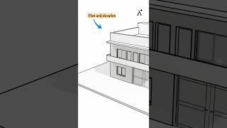
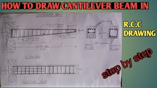
Longitudinal and Cross Section of a Cantilever Beam
Enroll to start learning
You’ve not yet enrolled in this course. Please enroll for free to listen to audio lessons, classroom podcasts and take practice test.
Interactive Audio Lesson
Listen to a student-teacher conversation explaining the topic in a relatable way.
Introduction to Cantilever Beams
🔒 Unlock Audio Lesson
Sign up and enroll to listen to this audio lesson

Good morning, class! Today we're diving into the fascinating world of cantilever beams. Who can tell me what a cantilever beam is?

It's a beam that is fixed at one end and free on the other!
Exactly! That means one end supports the entire load. Remember the acronym **P.O.A.**? It stands for **Point of Application** for the load, which occurs at the free end.

Can you explain how the loading affects the shape of the cross-section?
Of course! The shape might change based on the load distribution. For instance, larger loads may require deeper sections for strength.

What do we do to ensure safety in cantilever beams?
Good question! We ensure safe design by following reinforcement standards, which we will explore later.
To summarize, we learned what a cantilever beam is and its role in structural integrity. Remember that it has one fixed and one free end, which creates unique loading challenges.
Drawing Longitudinal and Cross Sections
🔒 Unlock Audio Lesson
Sign up and enroll to listen to this audio lesson

Next, let’s discuss how to effectively draw the longitudinal and cross sections of a cantilever beam. Who can remind us of the key components to include?
We need to show the size, support details, and reinforcement!
Exactly! When drawing these sections, you should also note the proportions. For example, a beam might have a larger section at the fixed end for support.

What size are we using for our exercises?
Great question! For our cantilever beam exercise, we will work with a size of 300mm x 300mm at the fixed end and taper down to 300mm x 150mm at the free end.
In conclusion, ensure that your drawings reflect both the overall dimensions and specific reinforcement details as discussed. This practice is essential for real-world applications.
Reinforcement Detailing
🔒 Unlock Audio Lesson
Sign up and enroll to listen to this audio lesson
Let's shift our focus to reinforcement detailing. Why is reinforcement critical in cantilever beams?
It helps to handle tension and compression forces!
Exactly! In our exercises, we'll often use #5 - 20ϕ bars for tensile reinforcement. Remember the mnemonic **R.C.** - which stands for Reinforced Concrete!
What about stirrups? How do they help?
Good question! Stirrups, such as the 2L - 6ϕ, provide shear resistance. They are typically spaced for effectiveness based on beam length.
So we have to consider both in our drawings?
Yes! A thorough understanding of reinforcement can greatly impact the functionality. Remember, **details matter!**
Introduction & Overview
Read summaries of the section's main ideas at different levels of detail.
Quick Overview
Standard
In this section, we discuss the characteristics of cantilever beams, specifically how to accurately draw their longitudinal and cross sections, including reinforcement detailing. The examples provided illustrate different configurations and sizes of cantilever beams used in practical applications.
Detailed
Detailed Summary
This section explores the principles behind the design of cantilever beams, which are pivotal structures in construction due to their ability to support loads at one end while being anchored at the other. A cantilever beam's cross-section varies based on its position and loading conditions, which affects the reinforcement detail necessary for practical applications.
Key Points Covered:
- Cantilever Beam Overview: Introduction to cantilever beams, emphasizing their support mechanisms and load distribution.
- Design Specifications: Detailed specifications for different exercises such as drawing longitudinal and cross sections for various beam configurations including fixed ends and free ends, with reinforcement details highlighted.
- Applications: Illustrative examples showcasing real-life scenarios where cantilever beams are used, reinforcing the importance of proper design and detailing.
In conclusion, mastering the concepts related to the longitudinal and cross sections of cantilever beams is crucial for future civil engineering applications and ensures structurally sound building designs.
Youtube Videos


Audio Book
Dive deep into the subject with an immersive audiobook experience.
Beam Dimensions and Projection
Chapter 1 of 2
🔒 Unlock Audio Chapter
Sign up and enroll to access the full audio experience
Chapter Content
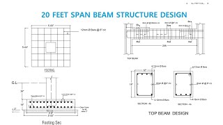
Clear projection from the face of RCC column = 2500mm
Size of column = 300mm x 300mm
Size of beam at fixed end = 300mm x 300mm
Size of beam at free end = 300mm x 150mm
Detailed Explanation
In this chunk, we discuss the dimensions of the cantilever beam and its projection from the column. The clear projection indicates how far the beam extends from the RCC column, which is crucial in determining its structural performance. The column size of 300mm x 300mm provides a solid support for the beam. The beam has a uniform dimension of 300mm x 300mm at the fixed end, which helps with load distribution, while the free end tapers down to 300mm x 150mm, reducing weight and material usage.
Examples & Analogies
Imagine a flagpole with a flag waving at the top. The pole (column) must be sturdy enough to hold the weight of the flag and withstand wind. Similarly, the dimensions of our cantilever beam must be optimized to balance strength (at the fixed end) and lightness (at the free end), just as a flagpole tapers to minimize material while ensuring stability.
Reinforcement Details
Chapter 2 of 2
🔒 Unlock Audio Chapter
Sign up and enroll to access the full audio experience
Chapter Content
Reinforcement main bars: #5 - 20ϕ with 2 bars curtailed at 1500mm from the support and show the curtailment plan.
Compression bars: #3 - 16ϕ
Stirrups: 2L - 6ϕ @ 200 c/c up to 1000mm from support and @ 300 c/c in remaining length.
Detailed Explanation
This chunk covers the reinforcement details for the cantilever beam. The main bars are specified as #5 - 20ϕ, indicating their size and quantity. These bars are critical for tension support in the beam. The term 'curtailed' means that some of the bars do not extend the full length of the beam; specifically, two bars stop 1500mm from the support. Compression bars support the top of the beam and are sized #3 - 16ϕ. Stirrups, used to hold the main bars in place and provide additional shear strength, are spaced differently: closer near the support for higher load areas and further apart in the middle.
Examples & Analogies
Consider a tightly wound balloon that you’re trying to keep inflated. The main bars are like the air filling the balloon, providing the primary support. However, too much air too close can make it pop, akin to the curtaining of the bars to maintain strength without excess stress. The stirrups are like the ties you might use to keep the balloon’s shape intact; they reinforce the structure and prevent any unwanted expansion or contraction.
Key Concepts
-
Cantilever Beam: A beam supported at one end only, commonly used in construction.
-
Longitudinal Section: The cut along the length of the beam that reveals internal structure.
-
Cross Section: The cut across the width of the beam showing details of its reinforcement.
-
Reinforcement Detailing: The specific layout and types of reinforcement used in a structure.
Examples & Applications
A cantilever beam used in a balcony that extends out from the building without external support.
The design of a swimming pool overhang that relies on a cantilever structure for stability.
Memory Aids
Interactive tools to help you remember key concepts
Rhymes
For beams that cantilever, just remember the end, one side is anchored, the other can bend.
Stories
Imagine a strong oak tree, growing out into the sky. It's sturdy at the base, but it sways as the wind blows. Just like this tree, a cantilever beam can extend and reach out, supported by its fixed base, illustrating an essential construction principle.
Memory Tools
C.A.L.C. - Cantilever beams require Adequate Loadbearing Capacity.
Acronyms
R.E.I.N.F.O.R.C.E - Reinforcement Enhances Internal Node Functionality and Overall Resistance to Compression and Extension.
Flash Cards
Glossary
- Cantilever Beam
A structural beam supported only at one end, allowing the other end to extend freely.
- Longitudinal Section
A vertical plane cut along the length of the structure, showing internal details.
- Cross Section
A vertical plane cut across the width of the structure, revealing internal components.
- Reinforcement
Steel bars or mesh incorporated to support and strengthen concrete.
- Stirrups
Loops of reinforcement placed around the main bars to provide shear support.
Reference links
Supplementary resources to enhance your learning experience.