
Advanced Tools in VLSI CAD
Enroll to start learning
You’ve not yet enrolled in this course. Please enroll for free to listen to audio lessons, classroom podcasts and take practice test.
Interactive Audio Lesson
Listen to a student-teacher conversation explaining the topic in a relatable way.
Introduction to CAD Tools
🔒 Unlock Audio Lesson
Sign up and enroll to listen to this audio lesson

Today, we're going to delve into advanced CAD tools used in VLSI design. Why do you think these tools are essential?

I think they help manage the complexity of modern designs, right?
Exactly! As VLSI designs become more complex, CAD tools help automate tasks and ensure high performance and efficiency. Can anyone name a specific type of CAD tool?

Are High-Level Synthesis tools one of them?
Correct! HLS tools allow designers to use higher-level programming languages instead of traditional RTL coding. This speeds up the development process.

What is RTL code again?
RTL stands for Register Transfer Level code, which is a type of representation used in describing digital circuits. Understanding this is crucial for using HLS effectively.
To summarize, advanced CAD tools enhance the design process by optimizing performance and ensuring reliability as complexity increases.
High-Level Synthesis Tools
🔒 Unlock Audio Lesson
Sign up and enroll to listen to this audio lesson

Let's dive deeper into High-Level Synthesis tools like Xilinx Vivado HLS and Cadence Stratus HLS. How do you think they improve the design process?
They automate the generation of RTL code from higher-level languages!
And I think they support optimization techniques like pipelining, right?
Exactly! Pipelining and loop unrolling are key techniques that help improve performance. Let's remember: High-Level Synthesis => Higher Abstraction Level + Fast Hardware Development.
Can we see how that impacts the time it takes to design chips?
Sure! By summarizing complex operations into simpler ones at a high level, designers can significantly reduce development time. So, in essence, HLS tools change the paradigm of hardware design.
In conclusion, HLS tools are vital in streamlining the VLSI design process by allowing high-level programming.
Static Timing Analysis Tools
🔒 Unlock Audio Lesson
Sign up and enroll to listen to this audio lesson
Static Timing Analysis tools are essential in verifying that designs operate correctly at the required clock speed. What are some well-known STA tools?
I've heard about Synopsys PrimeTime.
And Cadence Tempus is another one, isn’t it?
Correct! PrimeTime and Tempus check for critical timing issues without the need for running full simulations, ensuring designs meet setup and hold times.
How do they help in avoiding mistakes?
By analyzing timing paths and predicting potential timing violations early in the design process, these tools greatly enhance reliability and reduce costly rework later.
To wrap up, STA tools are crucial in maintaining design integrity by ensuring timing meets specifications before fabrication.
Integration of CAD Tools
🔒 Unlock Audio Lesson
Sign up and enroll to listen to this audio lesson
Integration of various CAD tools is vital for the efficiency of the design process. How do you think this interoperability benefits designers?
It eliminates errors that could arise from manual changes in one tool not being reflected in another.
And it helps save time by minimizing the need for redundant checks, right?
Exactly! By ensuring changes in one stage are automatically propagated through all stages, designers can achieve a smoother workflow. Let's remember: Interoperability = Efficiency.
What about data management? Does that play a role?
Certainly! Effective data management is necessary for handling large volumes of design data and maintaining consistency across iterations.
As a final point, integration and data management are the cornerstones of an efficient VLSI design flow.
Introduction & Overview
Read summaries of the section's main ideas at different levels of detail.
Quick Overview
Standard
The section explores advanced CAD tools revolutionizing VLSI design, including High-Level Synthesis, Design Compiler, Place-and-Route, Static Timing Analysis, and Formal Verification tools. It emphasizes their roles in optimizing design processes and enhancing efficiency through automation and machine learning.
Detailed
Advanced Tools in VLSI CAD
In the rapidly evolving field of VLSI (Very Large Scale Integration) design, advanced Computer-Aided Design (CAD) tools have become integral to managing increasing design complexities. These tools facilitate the creation of high-performance, power-efficient, and reliable VLSI systems. This section introduces various cutting-edge CAD tools and discusses their integration in the design flow and applications within contemporary VLSI design.
Key CAD Tools
- High-Level Synthesis (HLS) Tools transform higher-level programming languages like C/C++ and SystemC into synthesizable RTL code, enhancing design speed and efficiency.
- Xilinx Vivado HLS and Cadence Stratus HLS are prominent examples.
- Design Compiler Tools are critical for RTL synthesis, optimizing designs for area, power, and timing.
- Tools like Synopsys Design Compiler and Cadence Genus provide robust solutions for generating gate-level representations.
- Place-and-Route Tools ensure optimal physical layout, essential for minimizing wire lengths and meeting performance metrics.
- Cadence Innovus and Synopsys IC Compiler II exemplify effective solutions in this domain.
- Static Timing Analysis (STA) Tools check circuit timings without simulations, ensuring designs meet required clock frequencies.
- Synopsys PrimeTime and Cadence Tempus are widely utilized STA tools.
- Formal Verification Tools rigorously ensure designs meet specified properties through exhaustive checking.
- Examples include Cadence JasperGold and Synopsys VC Formal.
- Machine Learning and AI Tools leverage data from prior designs to enhance optimization processes in VLSI design, resulting in improved decision-making.
- Tools like Google’s TensorFlow and Synopsys’ machine learning algorithms enhance traditional methodologies.
Integration and Applications
The seamless integration of these advanced tools is paramount for effective VLSI design. This integration enhances tool interoperability, facilitates data management, and supports automated design flows, significantly reducing time-to-market.
Key applications include:
- SoC Design leveraging multiple functional blocks.
- 3D IC Design for improved performance and power efficiency.
- Low Power Design optimizations via machine learning.
Emerging Trends
Future developments may include quantum computing applications and increased reliance on AI to automate design processes further. The evolution of chiplet-based designs will also require tools to evolve to manage inter-chip communication.
In conclusion, advanced VLSI CAD tools represent a significant leap in the capability of designers to manage complexity and enhance the overall efficiency of the design process.
Youtube Videos
Audio Book
Dive deep into the subject with an immersive audiobook experience.
Introduction to Advanced CAD Tools
Chapter 1 of 10
🔒 Unlock Audio Chapter
Sign up and enroll to access the full audio experience
Chapter Content
The field of VLSI design has rapidly evolved with the development of more sophisticated CAD (Computer-Aided Design) tools. These advanced tools help designers handle the increasing complexity of VLSI systems, enabling them to create high-performance, power-efficient, and reliable chips. As VLSI designs scale, CAD tools are becoming more integrated, utilizing advanced algorithms, machine learning, and artificial intelligence to automate and optimize various design processes. This chapter introduces cutting-edge VLSI CAD tools, explores their integration within the design flow, and discusses their application in modern VLSI design.
Detailed Explanation
In VLSI design, designers use specialized software referred to as Computer-Aided Design (CAD) tools to create integrated circuits. As technology progresses, these tools have evolved to manage the complexity of increasingly intricate designs. Advanced CAD tools allow designers to automate tasks that were previously handled manually. This automation not only speeds up the design process but also helps in ensuring that the designs are more efficient, reliable, and consume less power. The integration of machine learning and AI into these tools allows them to improve over time, becoming better at predicting design outcomes and optimizing performance.
Examples & Analogies
Think of advanced CAD tools like a skilled chef in a restaurant. Initially, the chef might have to prepare every dish from scratch, following traditional recipes. As they gain experience, they begin to use modern cooking techniques and gadgets like sous-vide machines or food processors that streamline cooking. Similarly, CAD tools use advanced algorithms and AI to enhance VLSI design, automating and refining processes just like the chef improves their cooking efficiency and quality.
High-Level Synthesis (HLS) Tools
Chapter 2 of 10
🔒 Unlock Audio Chapter
Sign up and enroll to access the full audio experience
Chapter Content
High-Level Synthesis tools are transforming the way designers create hardware. Instead of manually writing RTL code, HLS tools allow designers to work at a higher level of abstraction, writing software code in C, C++, or SystemC, and automatically generating RTL code.
- Xilinx Vivado HLS: This tool transforms C/C++ code into synthesizable RTL code. It enables faster hardware development by automating the design of digital systems and providing optimization features like pipelining and loop unrolling.
- Cadence Stratus HLS: Cadence’s HLS tool accelerates the design of digital logic by providing high-level abstraction, automated RTL generation, and integration with the broader Cadence design environment for improved productivity and efficiency.
Detailed Explanation
High-Level Synthesis (HLS) tools are designed to streamline the hardware design process. Traditionally, designers would write Register Transfer Level (RTL) code, which is much lower-level and more complex. HLS tools allow designers to define their hardware using higher-level programming languages such as C or C++, making the design process more intuitive. Once the high-level code is written, the HLS tool automatically converts it into RTL code that can be synthesized into physical hardware. This automation saves time and reduces errors, facilitating faster development cycles. Notable examples include Xilinx Vivado HLS and Cadence Stratus HLS, which provide several optimization options to automate and improve the design process.
Examples & Analogies
Imagine constructing a house using detailed blueprints versus a ready-made house kit. Drawing detailed blueprints (writing RTL code) requires precise measurements, complex calculations, and attention to fine details. However, if you use a house kit (HLS tools), you only need to follow simpler instructions and put pieces together, saving time and effort. In the context of hardware design, HLS tools are the house kits that let designers focus on high-level design concepts without needing to get bogged down in low-level coding details.
Design Compiler Tools
Chapter 3 of 10
🔒 Unlock Audio Chapter
Sign up and enroll to access the full audio experience
Chapter Content
Design compilers are used for RTL synthesis, which converts high-level design descriptions into gate-level representations. These tools apply various optimization techniques to balance area, power, and performance while meeting timing constraints.
- Synopsys Design Compiler: This tool is a leading solution for logic synthesis, optimizing for power, area, and timing. It supports multi-level optimization and integrates seamlessly with static timing analysis (STA) and other verification tools.
- Cadence Genus Synthesis Solution: Genus provides RTL synthesis, optimization, and post-synthesis verification. It incorporates machine learning techniques to predict design behavior, making it more adaptive and efficient in achieving optimal synthesis results.
Detailed Explanation
Once the higher-level design is available, designers use design compiler tools for RTL synthesis. These tools transform the high-level descriptions into gate-level implementations, which dictate how the hardware will be physically built. Optimization is crucial here; design compilers must balance area (how much physical space is used), power consumption (how much energy the design uses), and performance (how quickly the design can operate). A couple of leading examples are Synopsys Design Compiler and Cadence Genus, both of which offer advanced features for optimizing these factors effectively.
Examples & Analogies
Consider a professional chef managing a restaurant menu. The chef must balance the menu items based on ingredients’ costs (area), how long they take to prepare (performance), and the popularity of certain dishes (power usage). Similarly, design compilers optimize hardware designs by balancing area, performance, and power to create efficient and effective end products.
Place-and-Route Tools
Chapter 4 of 10
🔒 Unlock Audio Chapter
Sign up and enroll to access the full audio experience
Chapter Content
Place-and-route tools are crucial in ensuring the physical layout of the VLSI design is optimal, minimizing wirelength and ensuring that timing and power requirements are met.
- Cadence Innovus: This tool automates the placement and routing of designs, optimizing for timing, power, and area. Innovus incorporates advanced algorithms for congestion management, timing closure, and signal integrity analysis.
- Synopsys IC Compiler II: IC Compiler II is widely used for physical design, offering high-quality placement, routing, and power optimization. It also provides advanced machine learning techniques to handle design rule checking (DRC) and layout versus schematic (LVS) verification.
Detailed Explanation
After synthesis, the next step in the design process is place-and-route, determining where each component of the circuit will physically go on the chip and how they will be connected. This optimization is vital for minimizing power loss and ensuring the system operates reliably at high speeds. Tools like Cadence Innovus and Synopsys IC Compiler II automate the layout process, managing complex algorithms to ensure optimal placement and routing while addressing timing and power considerations.
Examples & Analogies
Think of place-and-route tools like a city planner designing the layout of a city. The planner must decide where buildings (circuit components) should be placed to ensure good accessibility, minimal traffic, and efficient use of resources. Similarly, these tools ensure that components are laid out on a microchip in a way that optimally uses space and ensures effective communication between parts.
Static Timing Analysis (STA) Tools
Chapter 5 of 10
🔒 Unlock Audio Chapter
Sign up and enroll to access the full audio experience
Chapter Content
Static Timing Analysis (STA) tools analyze the timing of a circuit without running simulations, checking for timing violations such as setup and hold time violations. These tools are essential in ensuring that the design operates at the required clock frequency.
- Synopsys PrimeTime: PrimeTime is one of the most widely used STA tools for analyzing timing performance. It performs detailed analysis of the design’s setup and hold times and generates reports for optimizing critical paths.
- Cadence Tempus: Tempus is another leading STA tool that offers high accuracy and scalability for large designs. It supports advanced timing analysis, including multi-corner, multi-mode analysis for complex designs.
Detailed Explanation
Static Timing Analysis (STA) is a method used to check if a circuit design meets its timing requirements without needing to simulate the actual operation of the circuit. By verifying timing constraints like setup and hold times, STA ensures that signals arrive at their destinations at the right times. Tools like Synopsys PrimeTime and Cadence Tempus play an essential role in this step, providing detailed timing reports to help designers identify critical paths that might cause delays in the functioning of the chip.
Examples & Analogies
Imagine a train schedule where trains must arrive at different stations on time. Static Timing Analysis is like a station manager verifying that each train can make its scheduled stops as planned, without delays. Just as the manager checks the schedule for potential conflicts and adjusts timings, STA tools ensure that electronic signals in a chip meet their timing requirements, thereby ensuring smooth operation.
Formal Verification Tools
Chapter 6 of 10
🔒 Unlock Audio Chapter
Sign up and enroll to access the full audio experience
Chapter Content
Formal verification tools are used to verify that a design is functionally correct and meets all specified properties. These tools perform exhaustive checks to ensure that the design behaves as expected in all possible conditions.
- Cadence JasperGold: This formal verification tool uses model checking, equivalence checking, and property checking to ensure that designs are free from errors. It provides fast, comprehensive coverage for complex SoC and ASIC designs.
- Synopsys VC Formal: This formal verification tool uses a combination of formal methods to ensure the correctness of VLSI designs. It supports equivalence checking, functional verification, and coverage analysis.
Detailed Explanation
Formal verification tools check whether a design meets its specifications and behaves correctly regardless of circumstances. These tools utilize mathematical methods to exhaustively verify every possible scenario, ensuring there are no hidden faults or errors. Cadence JasperGold and Synopsys VC Formal exemplify tools that implement these checks to ensure high-reliability designs, especially for complex systems like System-on-Chip (SoC) and Application-Specific Integrated Circuits (ASIC).
Examples & Analogies
Think of formal verification like a meticulous proofreader who goes through a book, checking every single word and sentence for errors before it's published. Just as the proofreader ensures there are no mistakes or inconsistencies, formal verification tools rigorously check designs to confirm they function as intended, saving time and resources in later stages of development.
Machine Learning and AI Tools for VLSI Design
Chapter 7 of 10
🔒 Unlock Audio Chapter
Sign up and enroll to access the full audio experience
Chapter Content
Emerging tools are now incorporating artificial intelligence (AI) and machine learning to optimize the design process. These tools learn from previous designs to predict the best optimization paths, automate repetitive tasks, and improve decision-making throughout the design flow.
- Google’s TensorFlow for VLSI: TensorFlow can be used for predictive analytics and optimization in VLSI design. It helps optimize design parameters such as power, area, and timing by analyzing large datasets from previous designs and predicting the best configurations for new designs.
- Machine Learning in Synopsys Tools: Synopsys has incorporated AI and machine learning algorithms into their design tools like IC Compiler II and Design Compiler, improving optimization for power, timing, and area by learning from design data and predicting the most efficient configurations.
Detailed Explanation
Machine Learning (ML) and Artificial Intelligence (AI) tools are transforming the VLSI design landscape. By analyzing vast amounts of historical design data, these tools can identify patterns and predict the most effective optimization strategies for new designs. Google’s TensorFlow and ML features in Synopsys tools enable designers to reduce resource usage and enhance performance metrics effectively by learning from past successes and failures.
Examples & Analogies
Consider how music streaming services use algorithms to recommend songs by learning listener preferences. In VLSI design, AI and ML tools use past projects to 'recommend' design strategies that worked best, helping designers make better decisions even before they begin creating a new design.
Integration of Advanced VLSI CAD Tools
Chapter 8 of 10
🔒 Unlock Audio Chapter
Sign up and enroll to access the full audio experience
Chapter Content
The integration of multiple CAD tools within the design flow is key to achieving a seamless and efficient design process. Advanced VLSI CAD tools work together in a unified environment, automating tasks and ensuring that the design meets all specifications.
- Tool Interoperability: Integration between tools such as synthesis, placement, routing, and verification ensures that changes in one stage of the design flow are automatically propagated to subsequent stages. This eliminates errors and reduces manual intervention.
- Data Management: Advanced VLSI CAD tools require effective data management to store and process large amounts of design data. This includes the use of cloud-based platforms for distributed processing and version control systems to manage design iterations and maintain design consistency.
- Automated Design Flows: Modern CAD tools support automated design flows, which allow designers to run end-to-end design cycles automatically, optimizing for specific goals such as power, area, and timing. These automated flows significantly reduce time-to-market for new products.
Detailed Explanation
The full potential of advanced VLSI CAD tools is realized when they work together seamlessly. Tool interoperability allows information and changes to flow among different stages of the design process, reducing errors and boosting efficiency. Data management solutions enable the handling of the massive datasets generated during design. Automated design flows allow for repetitive design tasks to be completed efficiently, significantly speeding up the product development cycle.
Examples & Analogies
Picture a well-orchestrated stage performance, where every musician knows their role, and their instruments are synchronized, making the performance seamless. Similarly, the integration of CAD tools allows for the smooth transition of data and processes throughout the design workflow, ensuring that all parts are harmonized towards successfully creating the final product.
Applications of Cutting-Edge VLSI CAD Tools
Chapter 9 of 10
🔒 Unlock Audio Chapter
Sign up and enroll to access the full audio experience
Chapter Content
The integration and use of advanced CAD tools enable several key applications in VLSI design, such as:
- SoC Design: System-on-chip (SoC) designs, which integrate multiple functional blocks (processors, memory, I/O), can be efficiently developed using advanced tools for synthesis, placement, routing, and verification.
- 3D IC Design: Tools like Synopsys IC Compiler II and Cadence Innovus support 3D IC design, which allows for stacking of multiple chips to improve performance and reduce power consumption.
- Low Power Design: Machine learning-based optimization techniques help in automatically adjusting the power consumption of the design, ensuring it meets energy constraints.
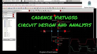
- Custom and Analog Design: Tools such as Cadence Virtuoso enable custom analog design and mixed-signal circuit development, providing automation for layout and verification in these designs.
Detailed Explanation
Advanced VLSI CAD tools have multiple applications in the field. For instance, they enable the development of System-on-Chip (SoC) designs, which combine various elements like processors and memory on a single chip for efficiency. Furthermore, they facilitate 3D IC design, stack multiple chips for enhanced performance, and leverage machine learning for low-power design optimization. They also assist in custom and analog designs, automating layout and verification tasks to improve precision and reduce design time.
Examples & Analogies
Think of advanced VLSI CAD tools as the architects and builders of a city. Just as architects design buildings (SoC), planners create multi-level structures (3D IC) for better land use, and engineers optimize for energy-efficient systems (Low Power Design), VLSI tools help create efficient, powerful, and specialized electronic systems. There are countless possibilities, just as cities are uniquely designed with different infrastructures.
Emerging Trends and Future of VLSI CAD Tools
Chapter 10 of 10
🔒 Unlock Audio Chapter
Sign up and enroll to access the full audio experience
Chapter Content
● Quantum Computing: As quantum computing becomes more prominent, VLSI CAD tools are starting to incorporate quantum algorithms to optimize circuit designs for quantum chips.
● AI-Driven Design Automation: The future of VLSI design automation lies in integrating more AI-driven techniques that can autonomously optimize designs by learning from vast amounts of design data.
● Chiplet-Based Design: With the increasing use of chiplet-based designs, where different functional units are integrated on a single package, VLSI CAD tools will need to evolve to handle inter-chip communication and power optimization across multiple chiplets.
Detailed Explanation
Looking ahead, VLSI CAD tools face exciting changes. Quantum computing introduces new possibilities, requiring tools that can handle quantum algorithms for circuit design. Moreover, AI-driven technologies are anticipated to take over more design optimization tasks, improving efficiency and accuracy through learned experiences. Meanwhile, chiplet-based designs, which combine different functional units into a package, will challenge tools to manage communication and power across multiple chips effectively.
Examples & Analogies
Consider the evolution of smartphones from basic call-and-text devices to multifunctional tablets that process data quickly and allow for various applications simultaneously. Just like smartphones have evolved to use new technologies while enhancing user experience, VLSI CAD tools must adapt to emerging technologies like quantum computing and AI to continue improving the design and manufacturing of complex electronic systems.
Key Concepts
-
High-Level Synthesis tools automate the conversion from high-level code to RTL.
-
Design Compiler tools optimize digital logic for power, area, and timing.
-
Place-and-route tools ensure physical layout optimization.
-
Static Timing Analysis tools verify timing without simulation.
Examples & Applications
Xilinx Vivado HLS allows developers to create complex algorithms in C/C++ and generate RTL promptly.
Synopsys Design Compiler applies multi-level optimization techniques to produce efficient gate-level designs.
Memory Aids
Interactive tools to help you remember key concepts
Rhymes
In VLSI, we synthesize, from C to RTL, we optimize.
Stories
Imagine a designer writing code in C, and with a click of a button, the CAD tool transforms it into a complex chip design—this is the magic of High-Level Synthesis!
Memory Tools
Remember ‘HLS’ as 'Higher Level Success' in synthesizing code!
Acronyms
STA
‘Synchronized Timing Analysis’ for perfecting design timings!
Flash Cards
Glossary
- VLSI
Very Large Scale Integration, a technology to integrate many transistors into a single chip.
- CAD
Computer-Aided Design, software tools used for designing hardware.
- HLS
High-Level Synthesis, a tool that converts high-level programming languages into RTL code.
- RTL
Register Transfer Level, a level of abstraction used to describe the operation of digital circuits.
- STA
Static Timing Analysis, a method to verify timing in circuits without simulation.
- SoC
System-on-Chip, an integrated circuit that incorporates all components of a computer or other electronic system.
- AI
Artificial Intelligence, simulation of human intelligence in machines.
Reference links
Supplementary resources to enhance your learning experience.