
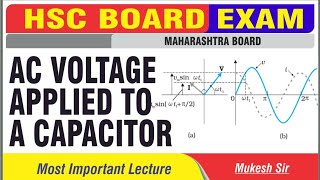
AC VOLTAGE APPLIED TO A CAPACITOR
Enroll to start learning
You’ve not yet enrolled in this course. Please enroll for free to listen to audio lessons, classroom podcasts and take practice test.
Interactive Audio Lesson
Listen to a student-teacher conversation explaining the topic in a relatable way.
Introduction to Capacitance in AC Circuits
🔒 Unlock Audio Lesson
Sign up and enroll to listen to this audio lesson

Today, we're going to explore how capacitors behave when connected to an AC source. Can anyone tell me what happens to a capacitor in a DC circuit?

In a DC circuit, a capacitor charges until it reaches the supply voltage and then stops the current.
That's right! Now, in an AC circuit, the situation is different. The current through the capacitor does not stop. Can anyone guess why?

Because the voltage is constantly changing polarity?
Exactly! The capacitor charges and discharges repeatedly as the AC cycle progresses. This leads us to the concept of instantaneous voltage across the capacitor.
Current-Voltage Relationship in Capacitors
🔒 Unlock Audio Lesson
Sign up and enroll to listen to this audio lesson

Let’s look at the equation for the voltage across a capacitor: V = q/C. What can you tell me about the current in relation to voltage?

The current is the rate of change of charge with time. So, it would be related to how fast the capacitor is charged, right?
Exactly! The current can be expressed as i = C * dv/dt. In an AC circuit, this means the current leads the voltage by π/2 radians. Can anyone visualize what that means?
So, the current reaches its peak before the voltage does.
Capacitive Reactance
🔒 Unlock Audio Lesson
Sign up and enroll to listen to this audio lesson
Now let's talk about capacitive reactance. Can someone explain what that is?
Isn't it the opposition that a capacitor offers to AC? It depends on the frequency and capacitance?
Correct! Capacitive reactance is given by X_c = 1/(ωC). This means as the frequency of the AC source increases, the reactance decreases!

So, if the frequency increases, does that mean the current also increases?
Yes! That's spot on. This relationship helps us understand how capacitors behave in AC circuits versus DC circuits.
Power in Capacitive Circuits
🔒 Unlock Audio Lesson
Sign up and enroll to listen to this audio lesson
Let's explore the power aspect. What do you think happens to the average power in a purely capacitive AC circuit?
It should be zero because the capacitor just stores and releases energy.
Exactly! The average power remains zero because all the energy is returned to the source, confirming that capacitors do not dissipate energy.
Summary and Recap
🔒 Unlock Audio Lesson
Sign up and enroll to listen to this audio lesson
To wrap up, can someone summarize what we've learned about AC in capacitors?
We learned that current leads voltage by π/2 in a capacitor, reactance decreases with frequency, and the average power is zero.
Great job! Always remember how each of these concepts interlinks to form our understanding of capacitive circuits.
Introduction & Overview
Read summaries of the section's main ideas at different levels of detail.
Quick Overview
Standard
In this section, we explore the behavior of capacitors when connected to AC sources, highlighting how the current leads the voltage and defining important concepts such as capacitive reactance. We also discuss the implications for power in these circuits, emphasizing that while AC flows through capacitors, the average power dissipation remains zero.
Detailed
AC Voltage Applied to a Capacitor
When an AC voltage is applied to a capacitor, unlike in a direct current (DC) circuit, the capacitor continuously charges and discharges, allowing current to oscillate. The section elaborates on how the instantaneous voltage across a capacitor relates to the charge and capacitance with the equation v = q/C.
Using Kirchhoff's loop rules, we find that the current is given by the derivative of charge, leading to the relation i = wC * v_m * cos(wt), where v_m is the peak voltage. The current reaches its maximum value ahead of the voltage by a phase difference of π/2 radians.
In capacitive circuits, the concept of capacitive reactance (
X_c = 1/(wC)
), helps to describe the opposition a capacitor presents to AC. This reactance inversely affects the relationship between current and frequency: as frequency increases, capacitive reactance decreases, allowing greater current.
The average power consumed over a cycle remains zero in an ideal capacitor as the energy stored in the capacitor during charging is returned during discharging. This characteristic reinforces the notion of AC circuits where energy can oscillate in capacitive systems without net energy loss. This section builds a foundation for understanding more complex reactive components in AC circuits.
Youtube Videos


Audio Book
Dive deep into the subject with an immersive audiobook experience.
Introduction to Capacitor in AC Circuits
Chapter 1 of 7
🔒 Unlock Audio Chapter
Sign up and enroll to access the full audio experience
Chapter Content
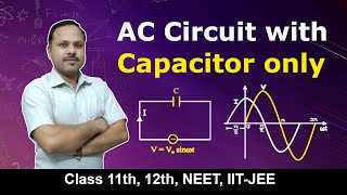
Figure 7.7 shows an ac source e generating ac voltage v = v sin wt connected to a capacitor only, a purely capacitive ac circuit. When a capacitor is connected to a voltage source in a dc circuit, current will flow for the short time required to charge the capacitor. As charge accumulates on the capacitor plates, the voltage across them increases, opposing the current.
Detailed Explanation
In this chunk, we discuss how a capacitor interacts in an AC circuit. When connected to an alternating current supply, the capacitor does not behave like it does in a direct current (DC) scenario. In DC, it initially allows current to flow while charging up to a certain voltage, after which the current stops. In AC, however, the current continuously reverses direction, causing the capacitor to charge and discharge periodically.
Examples & Analogies
Think of a water tank that fills up when water flows in and empties out when water flows back. In a DC circuit, the tank fills until it reaches a certain level and then the flow stops. In an AC circuit, the water continually fills and drains as the pressure changes direction, similar to how a capacitor charges and discharges in response to AC voltage.
Charge and Voltage Relationship in AC
Chapter 2 of 7
🔒 Unlock Audio Chapter
Sign up and enroll to access the full audio experience
Chapter Content
Let q be the charge on the capacitor at any time t. The instantaneous voltage v across the capacitor is q / C. From the Kirchhoff’s loop rule, the voltage across the source and the capacitor are equal, q / C = v sin(wt).
Detailed Explanation
Here, we establish a mathematical relationship between the charge (q) on the capacitor and the voltage (v) across it. The voltage across a capacitor is given by the formula v = q / C, where C is the capacitance. In an AC circuit, as the voltage from the source varies sinusoidally, the expression q / C = v sin(wt) shows that the voltage across the capacitor is induced by the changing charge that is affected by the alternating current.
Examples & Analogies
Imagine that the water tank mentioned earlier is also connected to a pressure gauge. As water flows in and out (in rhythm with the changing voltage), the pressure in the tank (analogous to the voltage across the capacitor) changes according to how full the tank is. The gauge fluctuates up and down even though the total volume of water (representing the charge) may remain constant over a given period.
Current Through the Capacitor
Chapter 3 of 7
🔒 Unlock Audio Chapter
Sign up and enroll to access the full audio experience
Chapter Content
To find the current, we use the relation i = dq/dt. By deriving this, we have i = vC sin(wt) = wC v cos(wt).
Detailed Explanation
This section focuses on determining the current flowing through the capacitor as it relates to the capacitor’s charge. The equation i = dq/dt highlights that the current is the rate of change of charge over time. When applying this to an AC voltage, the current is expressed as a function of time, showing that it leads the voltage by a phase of π/2 (90 degrees). This means that at the moment when the voltage is at its peak, the current reaches its peak value earlier.
Examples & Analogies
Using the tank example again, imagine that the water flows into and out of the tank at different times. The rate of filling (current) reacts faster than the overall height of water (voltage). When you turn off the water supply and then turn it back on quickly, the gauge (voltage) hits a peak after the inflow has already peaked, illustrating how the current can change faster than the voltage.
Capacitive Reactance
Chapter 4 of 7
🔒 Unlock Audio Chapter
Sign up and enroll to access the full audio experience
Chapter Content
Comparing it to i = v / R for a purely resistive circuit, we find that (1/wC) plays the role of resistance. It is called capacitive reactance and is denoted by X_c, where X_c = 1/wC.
Detailed Explanation
In this chunk, we define capacitive reactance (X_c), which acts similarly to resistance in a resistive circuit, but inversely. This means that as the frequency of the AC voltage increases, the capacitive reactance decreases, allowing more current to flow through the capacitor. This indicates that capacitors impede AC signals differently than DC signals.
Examples & Analogies
Consider a narrow river where water flows quickly (high frequency), allowing for little blockage (low reactance). If you widen the river (decrease frequency), the water encounters resistance (high reactance) and doesn't flow as freely. This analogy helps visualize how capacitors behave under varying frequencies of AC.
Current Lead in AC Circuits
Chapter 5 of 7
🔒 Unlock Audio Chapter
Sign up and enroll to access the full audio experience
Chapter Content
A comparison of Eq. (7.16) with the equation of source voltage shows that the current is π/2 ahead of voltage.
Detailed Explanation
This chunk emphasizes the lead of current over voltage in a capacitive circuit, measured as π/2 radians or 90 degrees. This lead demonstrates a crucial characteristic of capacitors in AC circuits. Understanding this time relationship is essential for analyzing AC circuits' behavior.
Examples & Analogies
If you think of the current and voltage as two people dancing, the person representing current would take a step forward (peak) before the person representing voltage does. This portrays their relationship during the alternating cycle, where the current moves ahead of the voltage.
Instantaneous Power in Capacitors
Chapter 6 of 7
🔒 Unlock Audio Chapter
Sign up and enroll to access the full audio experience
Chapter Content
The instantaneous power supplied to the capacitor is p = i v = (i v cos(ωt) sin(ωt)). The average power P equals 0 since the average of sin(2ωt) over a complete cycle is zero.
Detailed Explanation
In this section, we see how to compute instantaneous power in an AC circuit involving a capacitor. It essentially combines the current and voltage expressions and reflects the fluctuating nature of power. Importantly, while current flows, the average power consumed by the capacitor over time is confirmed to be zero, indicating that capacitors do not dissipate energy.
Examples & Analogies
If you were to continuously fill and drain the water tank (like the current in an AC circuit), for every cycle of filling and draining, the overall energy used averages out to zero because it effectively returns to the original state - no work is done at the end of the process.
Conclusion on Capacitors in AC Circuits
Chapter 7 of 7
🔒 Unlock Audio Chapter
Sign up and enroll to access the full audio experience
Chapter Content
Thus, we see that in the case of an inductor, the current lags the voltage by π/2 and in the case of a capacitor, the current leads the voltage by π/2.
Detailed Explanation
Finally, we summarize the contrasting behaviors of inductors and capacitors in AC circuits regarding their voltage and current relationships. This highlights an essential principle in AC circuit analysis that informs subsequent studies of complex circuits.
Examples & Analogies
Think of inductors and capacitors as two people in a three-legged race – one consistently lags behind (the inductor), while the other always manages to get ahead (the capacitor). This analogy encapsulates how they interact with alternating voltage and current.
Key Concepts
-
Capacitors charge and discharge in AC circuits.
-
Instantaneous voltage and charge are linked via v = q/C.
-
Current through a capacitor lags the voltage by π/2.
-
Capacitive reactance affects the flow of AC.
-
Average power in an ideal capacitor over one cycle is zero.
Examples & Applications
When an AC voltage of 220V is applied to a 20µF capacitor, the peak current can be calculated using the capacitive reactance.
If the frequency of the AC source doubles in a capacitive circuit, the current will increase as the capacitive reactance decreases.
Memory Aids
Interactive tools to help you remember key concepts
Rhymes
With frequency high, reactance is low, current can surge, watch it go!
Stories
Imagine a capacitor as a superhero, always charging up for a quick discharge. It can quickly jump to action but always takes the time to reset and start anew.
Memory Tools
Remember: 'CAP' for Capacitance leads to Altenerating Power loss being zero.
Acronyms
PIECE
**P**eak current leads **I**nstantaneous voltage **E**xhibiting **C**apacitive **E**nergy exchange.
Flash Cards
Glossary
- Capacitive Reactance
The opposition that a capacitor presents to alternating current, denoted as X_c = 1/(ωC).
- Instantaneous Voltage
The voltage across a capacitor at any specific moment during the AC cycle.
- Phase Difference
The angle in degrees or radians by which one wave leads or lags another, notably π/2 for current and voltage in a capacitor.
Reference links
Supplementary resources to enhance your learning experience.