
AC Voltage Applied to a Resistor
Enroll to start learning
You’ve not yet enrolled in this course. Please enroll for free to listen to audio lessons, classroom podcasts and take practice test.
Interactive Audio Lesson
Listen to a student-teacher conversation explaining the topic in a relatable way.
Introduction to AC Voltage and Resistor
🔒 Unlock Audio Lesson
Sign up and enroll to listen to this audio lesson

Welcome, everyone! Today we are going to explore what happens when we apply alternating current, or AC voltage, to a resistor. Can anyone tell me what AC voltage looks like?

Isn't it like a wave that goes up and down?
Exactly! AC voltage varies with time and can be represented by the equation v = v_m sin(ωt). Here, v_m is the peak voltage. Now, if we connect this to a resistor, we can find the current through it using Ohm's Law.

So, what's Ohm's Law for AC circuits?
Great question! It's similar to DC circuits. We use $i = \frac{v_m}{R} \sin(ωt)$. This tells us that the current is directly proportional to the voltage divided by the resistance.

And does that mean the current also varies like the voltage?
Absolutely! The current also varies sinusoidally, and both current and voltage are in phase in this case.

Does that mean they reach their maximum and minimum values at the same time?
Correct! This points us to an important characteristic of resistors in AC circuits—both waveforms are synchronized.
To summarize, we learned that in AC circuits, the voltage and current through a resistor reach their maximum and minimum values simultaneously. This is a fundamental concept in electrical engineering.
Power Dissipation in AC Circuits
🔒 Unlock Audio Lesson
Sign up and enroll to listen to this audio lesson

Now, let’s delve into how we calculate power in these circuits. The average power dissipated in a resistor is given by the formula $P_{avg} = \frac{1}{2} i_m^2 R$. Can someone remind me what $i_m$ represents?
It's the peak current, right?
That's correct! To bridge it with DC circuits, we often use root mean square values. Can anyone explain what rms current is?
Isn't rms current the average value that gives us the same power as DC?
Spot on! We define it as $I = \frac{i_m}{\sqrt{2}}$. The same applies for voltage. What would the rms voltage be?
It's $V = \frac{v_m}{\sqrt{2}}$!
Exactly! The average power can then also be expressed as $P = IV$, which reflects the similarity between AC and DC circuits.
So, even though we're dealing with sinusoidal values, we can still compute power in a relatable way?
Absolutely! Now, to recap, we’ve covered how power is determined for AC circuits, and how rms values help us understand and calculate that power effectively.
Characteristics of AC Resistor Circuits
🔒 Unlock Audio Lesson
Sign up and enroll to listen to this audio lesson
Let’s now discuss a critical takeaway: the phase relationship in AC circuits. In resistors, both current and voltage are in phase. Why do you think that's significant?
Because it means we can use the same formulas for AC and DC power?
Great observation! This allows us to apply similar techniques in different contexts. Also, remember that average power, in this case, is not zero even though the individual current flows oscillate.
Why is that? I thought average could be zero if there's oscillation.
Good question! Although instantaneous current oscillates, when squared and averaged over a cycle, the result is a positive value. Thus, Joule heating occurs—meaning energy is dissipated.
Does that mean in practice something like a resistor will get hot?
That's correct! The energy consumed translates to heat, which is why resistors are often rated for power dissipation.
In summary, we now understand that power in resistive circuits remains positive due to the consistent relationship between current and voltage sine waves.
Introduction & Overview
Read summaries of the section's main ideas at different levels of detail.
Quick Overview
Standard
The section explains the relationship between AC voltage and resistance, focusing on the key characteristics of AC circuits. It highlights how the applied AC voltage leads to a sinusoidal current, the phase relationships between them, and how power dissipation is calculated with reference to root mean square (rms) values.
Detailed
Detailed Summary
In this section, we explore the behavior of AC voltage when applied to a pure resistor. The voltage across the resistor is expressed mathematically as:
$$v = v_m \sin(\omega t)$$
where $v_m$ is the amplitude of the voltage, and $\omega$ is the angular frequency. The current through the resistor can be determined using Ohm's law for AC:
$$i = \frac{v_m}{R} \sin(\omega t)$$
The significant points discussed include:
1. In-Phase Relationship: The voltage and current are in phase in a resistive AC circuit, meaning they reach their maximum and minimum values at the same time.
2. Power Dissipation: The average power dissipated in the resistor is calculated using the formula:
$$P_{avg} = \frac{1}{2} i_m^2 R$$ where $i_m$ is the peak current. This leads to the introduction of root mean square (rms) current:
$$I = \frac{i_m}{\sqrt{2}}$$
3. rms Voltage: Similarly, the rms voltage related to $v_m$ is given by:
$$V = \frac{v_m}{\sqrt{2}}$$
4. Average Power in terms of rms Values: The power can also be expressed in terms of rms values as:
$$P = IV = I^2R$$
This section illustrates the essential principles of AC circuits and provides foundational knowledge for understanding more complex AC behaviors observed in other components like inductors and capacitors.
Youtube Videos


Audio Book
Dive deep into the subject with an immersive audiobook experience.
Introduction to AC Voltage Across a Resistor
Chapter 1 of 4
🔒 Unlock Audio Chapter
Sign up and enroll to access the full audio experience
Chapter Content
Figure 7.1 shows a resistor connected to a source ε of ac voltage. The symbol for an ac source in a circuit diagram is . We consider a source which produces sinusoidally varying potential difference across its terminals. Let this potential difference, also called ac voltage, be given by
v = v_m sin(ωt) (7.1)
where v_m is the amplitude of the oscillating potential difference and ω is its angular frequency.
Detailed Explanation
In this section, we introduce the concept of alternating current (AC) voltage applied to a resistor. When we connect a resistor to an AC voltage source, it delivers a voltage that varies sinusoidally over time. The mathematical expression v = v_m sin(ωt) provides us with a clear formula where v_m represents the highest voltage (peak voltage) reached in the cycle, and ω refers to the rate of oscillation or frequency of the AC signal. This establishes the basic understanding of how AC voltage behaves in circuits.
Examples & Analogies
Think of the AC voltage as the rhythm of a song, where the amplitude (v_m) is like the highest note played, and the angular frequency (ω) determines how quickly the notes change. Just like a song has a catchy beat that varies in intensity, AC voltage fluctuates over time.
Finding Current Using Kirchhoff’s Loop Rule
Chapter 2 of 4
🔒 Unlock Audio Chapter
Sign up and enroll to access the full audio experience
Chapter Content
To find the value of current through the resistor, we apply Kirchhoff’s loop rule (∑ ε(t) = 0), to the circuit shown in Fig. 7.1 to get
v_m sin(ωt) = iR
or
i = (v_m/R) sin(ωt) (7.2)
Detailed Explanation
Using Kirchhoff’s loop rule, which states that the total sum of electrical potential differences around any closed circuit must equal zero, we find the current (i) through the resistor directly related to the AC voltage. The equation v_m sin(ωt) represents the instantaneous voltage across the resistor, and by rearranging it, we derive the current in the form of i = (v_m/R) sin(ωt). This further illustrates how both current and voltage are sinusoidal and vary with time.
Examples & Analogies
Imagine a water hose connected to a pump. The AC voltage is like the pressure in the hose that makes water flow, and the resistor is like a nozzle that controls the water flow rate. When we measure how much water flows through the nozzle at any given moment, we see the flow (current) changes just like the pressure (voltage) changes over time.
Phase Relationship Between Voltage and Current
Chapter 3 of 4
🔒 Unlock Audio Chapter
Sign up and enroll to access the full audio experience
Chapter Content
Since R is a constant, we can write this equation as
i = i_m sin(ωt) (7.2)
where the current amplitude i_m is given by
i_m = v_m/R (7.3)
Equation (7.3) is Ohm’s law, which for resistors works equally well for both AC and DC voltages.
Detailed Explanation
The equation i = i_m sin(ωt) shows that the current through the resistor also varies sinusoidally with the same frequency as the voltage. The maximum current value (i_m) is determined by Ohm's Law, which states that current is voltage divided by resistance. This relationship holds true for both AC and DC, confirming that the basic principles of resistance apply regardless of the type of current.
Examples & Analogies
Picture a bicycle moving smoothly along a circular track. The current is akin to the bike’s speed, affected by the terrain (resistor). As the bike's speed fluctuates with laps (voltage changes), the relationship remains consistent, and the bike will eventually go faster or slower depending on how steep the track becomes.
Average Power Dissipation in a Resistor
Chapter 4 of 4
🔒 Unlock Audio Chapter
Sign up and enroll to access the full audio experience
Chapter Content
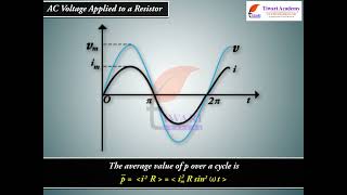
The voltage across a pure resistor and the current through it, given by Eqs. (7.1) and (7.2), are plotted as a function of time in Fig. 7.2. Note, in particular that both v and i reach zero, minimum and maximum values at the same time. Clearly, the voltage and current are in phase with each other.
Thus, the average current is zero, the average power consumed is given by
P = (1/2) i_m^2 R.
Detailed Explanation
In an ideal resistor, the voltage and current are fully synchronized (in phase), meaning they reach their peaks and troughs together. The average current over a complete cycle is calculated to show that while the instantaneous values might fluctuate, the average is maintained at a defined power level, mathematically given by P = (1/2) i_m^2 R. This indicates that energy is continuously being consumed in the form of heat due to Joule heating.
Examples & Analogies
Imagine a campfire where the flames leap up and down. The flames represent the current and the energy being released as heat. While the intensity of the flames varies, over the course of an evening, the average warmth (power dissipation) felt from the fire remains consistent.
Key Concepts
-
AC Voltage: Varies sinusoidally, leading to a sinusoidally varying current in resistive circuits.
-
Ohm's Law in AC: i = (v_m / R) * sin(ωt), demonstrating the relationship between voltage, current, and resistance.
-
In-Phase Relationship: Current and voltage in an AC resistive circuit are in phase, indicating synchronous peaks and troughs.
-
RMS Values: Effective voltage and current represented as V = v_m/sqrt(2) and I = i_m/sqrt(2) to calculate average power.
-
Average Power Dissipation: Power in AC circuits is calculated using P = I^2 R, requiring rms values.
Examples & Applications
When a 220V AC voltage is applied to a resistor of 100Ω, the peak current is calculated using Ohm's Law, resulting in a peak current of 2.2A.
In an AC circuit with a peak voltage of 311V, the corresponding rms voltage is 220V, further allowing us to calculate average power.
Memory Aids
Interactive tools to help you remember key concepts
Rhymes
When AC flows, it is not slow; with a resistor, in phase, they glow.
Stories
Imagine AC current dancing around a room with voltage. They move together in sync, illuminating the resistor warmly, ensuring energy gets used effectively.
Memory Tools
Power in Resistors: P=I^2R for Ohm’s great favor. (PIR)
Acronyms
RMS
Really Magnifies Stability—representing that RMS shows the effective current.
Flash Cards
Glossary
- AC Voltage
Voltage that varies with time in a sinusoidal manner, typically in the form of a sine wave.
- Resistor
An electrical component that resists the flow of current, causing power to be dissipated as heat.
- RMS Current
The root mean square current value, representing the effective current in an AC circuit.
- Power Dissipation
The process by which electrical energy is converted into heat in a resistor.
- Ohm's Law
A fundamental principle that states the current through a conductor between two points is directly proportional to the voltage across the two points.
- Joule Heating
The heat produced in a resistor when an electric current passes through it.
Reference links
Supplementary resources to enhance your learning experience.