
AC Voltage Applied to a Series LCR Circuit
Enroll to start learning
You’ve not yet enrolled in this course. Please enroll for free to listen to audio lessons, classroom podcasts and take practice test.
Interactive Audio Lesson
Listen to a student-teacher conversation explaining the topic in a relatable way.
Introduction to LCR Circuit
🔒 Unlock Audio Lesson
Sign up and enroll to listen to this audio lesson

Today we will explore the behavior of a series LCR circuit when connected to an alternating current (AC) voltage. What components do we have in an LCR circuit?

We have an inductor, a capacitor, and a resistor.
That's correct! Now, can anyone tell me how these components affect the circuit's response to AC voltage?

The inductor and capacitor will create reactance, which affects the current.
Exactly! The inductor resists changes in current, while the capacitor opposes changes in voltage. This leads us to define impedance and phase relationships.

What is impedance?
Impedance is the total opposition that a circuit offers to the flow of alternating current. We will learn how to calculate it shortly!
Applying Kirchhoff’s Loop Rule
🔒 Unlock Audio Lesson
Sign up and enroll to listen to this audio lesson

Next, let’s apply Kirchhoff’s loop rule to our circuit. The equation we derive will help us understand how voltage and current relate. Who can help me write the equation?

I think it's L di/dt + iR + (q/C) = v.
Great job! Each term represents a component of the circuit: the inductor, resistor, and capacitor. Now, how can we express the current using this equation?
We can differentiate the voltage with respect to time to find the current.
That's right! The current can be expressed in terms of the charge on the capacitor. Excellent work!
Understanding Phase Relationships
🔒 Unlock Audio Lesson
Sign up and enroll to listen to this audio lesson
Now, let's discuss the phase relationships. How does the current behave with respect to the voltages across the inductor, resistor, and capacitor?
The current lags behind the voltage in an inductor, while it leads the voltage in a capacitor.
Perfect! The current lags the voltage across the inductor by 90 degrees and leads the voltage across the capacitor by 90 degrees. Thus, we can calculate the total phase difference!
How do we find the phase difference mathematically?
We find it by using the tangent of the phase angle to relate the reactances and resistance: \(\tan(\phi) = \frac{X_L - X_C}{R}\).
Resonance in LCR Circuits
🔒 Unlock Audio Lesson
Sign up and enroll to listen to this audio lesson
Let's explore the idea of resonance in our LCR circuit. What happens at resonance?
The current reaches its maximum amplitude!
Correct! Resonance occurs when the inductive and capacitive reactances are equal. Do you remember how we define the resonant frequency?
Yes! It's given by \(\omega_0 = \frac{1}{\sqrt{LC}}\).
Well done! At this frequency, the impedance is minimized and the circuit can draw maximum current. Remember that the voltages across L and C effectively cancel out!
Power Calculations
🔒 Unlock Audio Lesson
Sign up and enroll to listen to this audio lesson
Finally, let's calculate average power in the circuit. Recall the equation we use to relate current, voltage, and phase angle?
It's \(P = VI \cos(\phi)\), where \(P\) is the power, \(V\) is the voltage, and \(I\) is the current!
Exactly! And remember, the term \(\cos(\phi)\) is known as the power factor, which tells us the efficiency of the power use.
Can the power factor be zero?
Yes, it can happen in purely inductive or capacitive circuits as the average power would then equal zero despite the current flowing. Good question!
Introduction & Overview
Read summaries of the section's main ideas at different levels of detail.
Quick Overview
Standard
In this section, the dynamics of a series LCR circuit under an alternating current (AC) voltage are explored. We will analyze the relationships between the voltage across its components, the current, impedance, and phase angles, while deriving the current amplitude and average power loss in the circuit.
Detailed
Detailed Summary
In this section, we delve into the behavior of a series LCR (Inductor-Capacitor-Resistor) circuit when subjected to an alternating current (AC) voltage source. The circuit is composed of a resistor (R), an inductor (L), and a capacitor (C) connected in series, each affecting the overall circuit performance.
Key Points Covered:
- Kirchhoff’s Loop Rule Application: The governing equation for the circuit is derived using Kirchhoff’s law:
$$ L \frac{di}{dt} + iR + \frac{q}{C} = v $$
where \(v = v_{m} \sin(\omega t)\). Here, \(q\) is the charge on the capacitor, and \(i\) is the instantaneous current.
- Phasor Diagram Solution: We construct phasors to represent the circuit's voltages (across R, L, and C) and the current. The peak voltages across each are related to the current amplitude, leading to the equations:
$$ V_{L} = i_{m} X_{L},\ V_{R} = i_{m} R, \ V_{C} = i_{m} X_{C} $$
- Impedance Concept: The total impedance \(Z\) of the circuit is defined by the relation:
$$ Z = \sqrt{R^{2} + (X_{L} - X_{C})^{2}} $$
where \(X_{L} = \omega L\) and \(X_{C} = \frac{1}{\omega C}\).
- Phase Relationships: The phase difference (\(\phi\)) between the source voltage and current is determined by the formula:
$$ \tan(\phi) = \frac{X_{L} - X_{C}}{R} $$
- Resonance: We examine how resonance occurs when \(X_{L} = X_{C}\) and the effect on the current amplitude, which becomes maximum at this condition. The resonant frequency is given by:
$$ \omega_{0} = \frac{1}{\sqrt{LC}} $$
- Average Power Calculation: The average power dissipated in the circuit is computed based on the current and voltage relationship and phase factor, ultimately expressed as:
$$ P = V_{I} \cos(\phi) $$
In summary, this section illustrates the intricate relationships within an LCR circuit subjected to an AC voltage source, emphasizing important concepts such as impedance, phase angles, resonant frequency, and power calculations.
Youtube Videos


Audio Book
Dive deep into the subject with an immersive audiobook experience.
Introduction to the Series LCR Circuit
Chapter 1 of 6
🔒 Unlock Audio Chapter
Sign up and enroll to access the full audio experience
Chapter Content
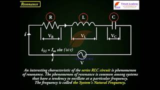
Figure 7.10 shows a series LCR circuit connected to an ac source e. As usual, we take the voltage of the source to be v = v sin wt.
Detailed Explanation
In this section, we are introducing the concept of a series LCR circuit, which consists of an inductor (L), capacitor (C), and resistor (R) connected in series with an alternating current (ac) voltage source. The source voltage is represented mathematically as v = v sin(wt), where 'v' is the amplitude and 'w' is the angular frequency. This sets the stage for analyzing current and voltage in the circuit under the influence of the applied ac voltage.
Examples & Analogies
Think of this circuit like a team dance performance where each dancer (elements L, C, and R) needs to sync their movements (the current and voltage) with the music (the ac voltage source). Just like in a dance, the timing between elements is crucial for an effective performance.
Applying Kirchhoff’s Loop Rule
Chapter 2 of 6
🔒 Unlock Audio Chapter
Sign up and enroll to access the full audio experience
Chapter Content
If q is the charge on the capacitor and i the current, at time t, we have, from Kirchhoff’s loop rule: di q L +iR + =v (7.20) dt C.
Detailed Explanation
This chunk introduces Kirchhoff’s Loop Rule, which states that the sum of the voltage sources in a closed loop is equal to the sum of the voltage drops across the elements. Here, 'q' represents the charge stored in the capacitor, 'i' is the current flowing through the circuit, and 'L', 'R', and 'C' are the inductor, resistor, and capacitor, respectively. The equation relates these quantities to the voltage provided by the source.
Examples & Analogies
Imagine a water tank system where the charge 'q' represents the amount of water in the tank (capacitor), current 'i' is the flow of water (current), and the height difference (voltage) is what drives the flow. Kirchhoff’s rule ensures that the total heights provide enough pressure for the flow, just like applying voltage helps with current in the circuit.
Phasor Diagram Solution
Chapter 3 of 6
🔒 Unlock Audio Chapter
Sign up and enroll to access the full audio experience
Chapter Content
From the circuit shown in Fig. 7.10, we see that the resistor, inductor, and capacitor are in series. Therefore, the ac current in each element is the same at any time. Let it be i = i sin(wt+f) (7.21)
Detailed Explanation
This chunk discusses how to analyze the circuit using phasors, which are graphical representations of the voltages and currents. In a series circuit, the current remains constant across all components. The expression i = i sin(wt+f) incorporates a phase shift 'f', which is crucial for understanding how the current and source voltage relate to each other in time.
Examples & Analogies
Think of phasors like the hands of a clock. The hour hand can be seen as the current (i), rotating at a steady pace (oscillating). The position of the minute hand can represent the voltage across the source. The angle between these hands (phase shift) shows how they relate to each other over time.
Impedance and Phase Angle
Chapter 4 of 6
🔒 Unlock Audio Chapter
Sign up and enroll to access the full audio experience
Chapter Content
The phasor relation whose vertical component gives the above equation is v + v + v = v (7.24) L R C.
Detailed Explanation
In this section, we derive the relationship between the voltages across the inductor, capacitor, and resistor by utilizing a phasor diagram. The total voltage from the source can be interpreted as a vector sum of the voltages across each component, leading to the concept of impedance (Z), which measures how much the circuit resists the flow of current.
Examples & Analogies
Consider trying to push three people on a swing, each with a rope (representing the voltages across R, L, and C). If you pull them slightly differently, you'll see how they can push back against you (impedance). The total effort required to push all three effectively is represented by the impedance.
Concept of Resonance
Chapter 5 of 6
🔒 Unlock Audio Chapter
Sign up and enroll to access the full audio experience
Chapter Content
An interesting characteristic of the series RLC circuit is the phenomenon of resonance.
Detailed Explanation
Resonance in an RLC circuit occurs when the inductive reactance equals the capacitive reactance at a particular frequency, known as the resonant frequency. At this point, the impedance is minimized, allowing maximum current to flow through the circuit. This section also explains how this principle is leveraged in devices such as radios.
Examples & Analogies
Imagine a child swinging on a swing set. If someone pushes them at just the right moment (the resonant frequency), they swing higher and higher. In the same way, circuits can resonate, leading to higher currents at specific frequencies which can be tuned for various applications.
Applications of Resonance
Chapter 6 of 6
🔒 Unlock Audio Chapter
Sign up and enroll to access the full audio experience
Chapter Content
Resonant circuits have a variety of applications, for example, in the tuning mechanism of a radio or a TV set.
Detailed Explanation
This chunk outlines how resonance can be used practically, particularly in radio technology. A resonant circuit can be adjusted to match the frequency of a desired radio station, allowing for clear reception by tuning to that specific frequency, exemplifying how resonance is achieved in practical scenarios.
Examples & Analogies
Think of tuning a guitar string. The ideal string vibrations resonate to produce a pleasant sound of a specific note. If you adjust the tension or length (similar to adjusting capacitance), you can match the desired note, just like adjusting the tuning of a radio to receive a preferred station.
Key Concepts
-
Series LCR Circuit: A circuit consisting of a resistor, inductor, and capacitor connected in series which has distinct behaviors under AC voltage.
-
Impedance (Z): Represents the total opposition a circuit presents to AC, encompassing resistance and reactance.
-
Phase Angle (φ): The angle by which the current lags or leads the voltage in an AC circuit, calculated based on reactance and resistance.
-
Resonance: A condition where reactances of inductors and capacitors cancel each other, resulting in maximum current flow.
-
Power Factor: It determines how effectively a circuit converts electric power into useful work and is calculated as the cosine of the phase angle.
Examples & Applications
Example 1: Calculate the average power in a series LCR circuit when given the resistive and reactive components.
Example 2: Determine the phase angle for a circuit with known values of R, XL, and XC.
Memory Aids
Interactive tools to help you remember key concepts
Rhymes
In an LCR circuit, when the waves align, the current is highest, resonance is fine.
Stories
Imagine an orchestra: the inductor and capacitor must be in sync to create beautiful sound or maximum current—this is resonance!
Memory Tools
Remember RLC for Resonance: R - Reactance, L - Lags, C - Leads.
Acronyms
Use the acronym 'PIR' for Power in Resistors
Power dissipated is measured in resistive loads!
Flash Cards
Glossary
- Impedance (Z)
The total opposition to current flow in an AC circuit, combining resistance and reactance.
- Reactance
The opposition offered by a capacitor or inductor to the change in current or voltage.
- Phase Angle (φ)
The angle difference between the voltage and current waveforms in an AC circuit.
- Resonance
A condition in a circuit at which the reactances are equal and maximum current flows.
- Power Factor (cos φ)
The ratio of the real power flowing to the load to the apparent power in the circuit.
Reference links
Supplementary resources to enhance your learning experience.