
System Description - 3.5.1
Enroll to start learning
You’ve not yet enrolled in this course. Please enroll for free to listen to audio lessons, classroom podcasts and take practice test.
Interactive Audio Lesson
Listen to a student-teacher conversation explaining the topic in a relatable way.
Introduction to RLC Circuit Components
🔒 Unlock Audio Lesson
Sign up and enroll to listen to this audio lesson

Today, we're diving into a key component of dynamic electrical systems—the series RLC circuit. Does anyone know what components are part of this circuit?

It includes a resistor, an inductor, and a capacitor, right?
Exactly! The resistor resists current flow, the inductor stores energy as a magnetic field, and the capacitor stores energy as an electric field. To remember this, think of 'RIC' - Resistor, Inductor, Capacitor.

What do these components actually do in the circuit?
Good question! They work together to determine how the circuit behaves in response to voltage. Each component contributes to the overall voltage-current relationships!
Voltage-Current Relationships
🔒 Unlock Audio Lesson
Sign up and enroll to listen to this audio lesson

Now, let's discuss the voltage-current relationships. The voltage across the resistor is given by Ohm's law. Can someone tell me how it's expressed?

It's VR = IR.
That's right! And for the inductor, we express voltage as VL = L dI/dt. Who can tell me how we represent the voltage for the capacitor?

It’s VC = (1/C) ∫Idt?
Perfect! Using these relationships, we can say that the total input voltage is the sum of the voltages across these components. Can anyone explain why this is important?
It helps us understand how the components share voltage under different conditions.
Exactly! This foundational knowledge leads us to our next topic—deriving the transfer function.
Deriving the Transfer Function
🔒 Unlock Audio Lesson
Sign up and enroll to listen to this audio lesson
Now, let’s derive the transfer function H(s). We start with the equation describing the sum of voltages. Can anyone give it a shot?
Vin(s) = I(s)(R + Ls + (1/(Cs))).
Correct! We can rearrange this to form the transfer function as H(s) = I(s)/Vin(s) = 1/(R + Ls + (1/(Cs))). Why do you think transfer functions are crucial in circuit analysis?
They help predict how the circuit will respond over time!
Exactly right! This allows engineers to design more effective and reliable circuits.
Introduction & Overview
Read summaries of the section's main ideas at different levels of detail.
Quick Overview
Standard
The section provides an overview of the series RLC circuit, detailing the components involved, their voltage-current relationships, and concludes with the derivation of the transfer function for the circuit. This description is crucial as it lays the groundwork for understanding dynamic systems in the context of electrical engineering.
Detailed
In this section, we explore the series RLC circuit, an essential foundational component in electrical engineering. The circuit comprises a resistor (R), which resists the flow of current; an inductor (L), which stores energy in a magnetic field; and a capacitor (C), which stores energy in an electric field. The voltage across each circuit component follows specific relationships: across the resistor, it is determined by Ohm's law (VR = IR), across the inductor, it is expressed through the rate of change of current (VL = L dI/dt), and across the capacitor, as an integration of current (VC = (1/C) ∫Idt). Leveraging these relationships, the sum of voltages around the circuit equals the input voltage. By taking the Laplace transform of these voltage equations, we derive the transfer function H(s), which articulates the relationship between the current (output) and the input voltage in the circuit as H(s) = I(s)/Vin(s) = 1/(R + Ls + (1/(Cs))). This transfer function forms the framework for analyzing and designing RLC circuits within the broader topic of dynamic systems.
Youtube Videos


Audio Book
Dive deep into the subject with an immersive audiobook experience.
Overview of the RLC Circuit
Chapter 1 of 6
🔒 Unlock Audio Chapter
Sign up and enroll to access the full audio experience
Chapter Content
Next, let’s look at an example from electrical engineering: the series RLC circuit, which consists of a resistor R, an inductor L, and a capacitor C connected in series.
Detailed Explanation
This chunk introduces the RLC circuit as an example of a dynamic system in electrical engineering. An RLC circuit is composed of three basic components: a resistor (R), an inductor (L), and a capacitor (C), which are arranged in series. This means that there is a single path for current to flow through all three elements, allowing us to analyze how the voltage and current interact within the circuit.
Examples & Analogies
You can think of the RLC circuit like a water system. The resistor is similar to a narrow section of pipe that restricts water flow (just as a resistor limits electrical current). The inductor can be likened to a water tank that holds water and can increase pressure (just like how an inductor stores energy in a magnetic field). The capacitor is like a bladder that stores water and releases it (similar to how a capacitor stores and releases electrical charge).
Components of the RLC Circuit
Chapter 2 of 6
🔒 Unlock Audio Chapter
Sign up and enroll to access the full audio experience
Chapter Content
System Description:
● Resistor (R): Resists the flow of current.
● Inductor (L): Stores energy in the form of a magnetic field.
● Capacitor (C): Stores energy in the form of an electric field.
Detailed Explanation
Each component in the RLC circuit serves a distinct function:
- The resistor (R) restricts the flow of electrical current, dissipating energy in the form of heat.
- The inductor (L) acts like an energy reservoir, storing energy when the current increases and releasing it when the current decreases. This happens due to its magnetic field that builds up around it as current flows.
- The capacitor (C) stores electrical charge and can release it back into the circuit, creating high voltages when needed, similarly to how a battery works. This of these components determines the circuit's behavior significantly.
Examples & Analogies
Imagine a water system:
- The resistor is like a faucet that can control the amount of water flowing through a pipe. The more you restrict the faucet, the less water can flow, which symbolizes how resistors limit current.
- The inductor is analogous to a water wheel; when water flows, it spins the wheel and stores energy in the form of motion (like how inductors store energy in a magnetic field).
- The capacitor can be compared to a rubber balloon. When you fill it with air (electric charge), it expands. When you release the air, the balloon contracts, representing how capacitors store and release electrical energy.
Voltage-Current Relationships
Chapter 3 of 6
🔒 Unlock Audio Chapter
Sign up and enroll to access the full audio experience
Chapter Content
Voltage-Current Relationship:
The voltage across each component in the circuit can be described by:
● Resistor: VR=IR
● Inductor: VL=LdIdt
● Capacitor: VC=1C∫Idt
Detailed Explanation
This chunk details how voltage and current are related for each component in the RLC circuit:
- For the resistor, Ohm’s Law states that the voltage across it (VR) is equal to the current (I) flowing through it multiplied by the resistance (R).
- For the inductor, the voltage across it (VL) is proportional to the rate of change of current over time (dI/dt), multiplied by its inductance (L).
- For the capacitor, the voltage (VC) is derived from the current that flows into it, represented as the integration of current over time divided by the capacitance (C). These equations are fundamental to analyzing circuit operation as they link voltage, current, and component properties.
Examples & Analogies
Consider a flowing river:
- The resistor is like a dam that controls how much water (current) can flow through at any time. The higher the dam (greater resistance), the more pressure (voltage) is needed for water to flow.
- The inductor is like a moving sailboat; it experiences a voltage proportional to how quickly it accelerates or changes direction, just like the inductor’s voltage relates to how the current changes.
- The capacitor can be visualized as a water tower; it fills and releases water. The height of the water tower represents the voltage, while the amount of water flowing into it represents the current over time.
Input Voltage Equation
Chapter 4 of 6
🔒 Unlock Audio Chapter
Sign up and enroll to access the full audio experience
Chapter Content
The sum of the voltages around the circuit is equal to the input voltage:
Vin(t)=VR+VL+VC=IR+LdIdt+1C∫Idt
Detailed Explanation
This chunk presents the fundamental voltage equation for the RLC circuit. According to Kirchhoff's voltage law, the total voltage in a closed loop must equal zero. In this case, the input voltage (Vin(t)) must equal the sum of the voltages across the resistor (VR), inductor (VL), and capacitor (VC). This relationship is crucial for analyzing the circuit's behavior, as it forms the basis for setting up equations involving input and component voltages. It shows how energy is conserved within the circuit.
Examples & Analogies
Think of this circuit like a water slide at an amusement park. The height of the slide is like the input voltage: it provides the energy for the water to flow down. As the water moves, it needs to overcome different obstacles (like the resistance of pipes, represented by the resistor, or the fluctuations in flow from the tank represented by the capacitor and inductor). Just as the total height of water (input voltage) at the top equals the energy needed to navigate the entire slide, the input voltage in the circuit equals the sum of voltages across each component.
Laplace Transform of the Circuit
Chapter 5 of 6
🔒 Unlock Audio Chapter
Sign up and enroll to access the full audio experience
Chapter Content
Taking the Laplace transform of the equation:
Vin(s)=I(s)R+I(s)Ls+I(s)1Cs
Detailed Explanation
In this chunk, we see the process of converting the time-domain voltage equation to the Laplace domain. Here, Vin(s) is the Laplace transform of the input voltage, and I(s) is the Laplace transform of the current. The Laplace transform change the functions of time into functions of a complex variable (s), which simplifies the algebra of differential equations, making them easier to solve. This is crucial in control systems as it allows engineers to analyze systems using algebra instead of calculus.
Examples & Analogies
Imagine you’re recording the water flow in a series of time-lapsed photographs instead of on video. The photographs capture the flow as snapshots, making it easier to see the patterns and changes over time. The Laplace transform does something similar for electrical signals, allowing engineers to analyze the overall performance of the circuit by breaking it down into manageable parts without having to solve complex differential equations in real-time.
Transfer Function Derivation
Chapter 6 of 6
🔒 Unlock Audio Chapter
Sign up and enroll to access the full audio experience
Chapter Content
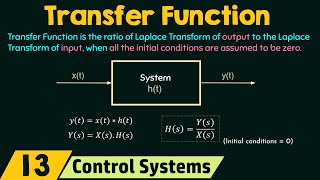
The transfer function H(s) is the ratio of the output (current I(s)) to the input voltage Vin(s):
H(s)=I(s)Vin(s)=1R+Ls+1Cs.
Detailed Explanation
The final chunk defines the transfer function (H(s)) of the RLC circuit, which is represented as the ratio of output current (I(s)) to the input voltage (Vin(s)). This transfer function captures how the circuit responds to input signals in the frequency domain, illustrating how it behaves in relation to various frequencies of input signals. Transfer functions are essential in control engineering, as they characterize the dynamics of a system and help predict how the system will respond to different inputs.
Examples & Analogies
You can think of the transfer function as your phone’s software responding to different app usage. Depending on which app you open (the input), your phone’s system will react in specific ways based on how it's programmed (the circuit's behavior). If you apply more pressure by running more apps simultaneously (changing the voltage/current input), the operational speed and capacity will vary, similar to how circuit components react to different input voltages.
Key Concepts
-
RLC Circuit: A circuit consisting of a resistor, an inductor, and a capacitor, which provides insights into dynamic system responses.
-
Voltage-Current Relationships: The relationships that govern how voltages across R, L, and C interact with the input voltage.
-
Transfer Function: The derived function that expresses the output current in relation to the input voltage.
Examples & Applications
In an RLC circuit with R = 10Ω, L = 5H, and C = 20F, the transfer function can predict how the circuit responds to changes in input voltage.
When a step voltage is applied to an RLC circuit, the transient response can be analyzed using the derived transfer function.
Memory Aids
Interactive tools to help you remember key concepts
Rhymes
RLC is bold and bright, Resistor, Inductor, Capacitor - they light up the night!
Stories
Imagine a factory where a resistor controls the flow of raw materials, an inductor saves energy for later, and a capacitor stores finished goods. Together, they run an efficient operation.
Memory Tools
Remember: 'Reds in the love can’—Resistor, Inductor, Capacitor—a sound to recall circuit essentials.
Acronyms
Think 'RIC' to recall Resistor, Inductor, Capacitor in the RLC Circuit.
Flash Cards
Glossary
- RLC Circuit
An electrical circuit consisting of a resistor (R), an inductor (L), and a capacitor (C) connected in series or parallel.
- Resistor
A component that resists the flow of electric current, converting electrical energy into heat.
- Inductor
A passive electrical component that stores energy in a magnetic field when electric current flows through it.
- Capacitor
A passive electronic component that stores energy in an electric field, capable of storing and releasing electrical energy.
- Transfer Function
A mathematical representation of the relationship between the input and output of a linear time-invariant (LTI) system in the frequency domain.
Reference links
Supplementary resources to enhance your learning experience.