
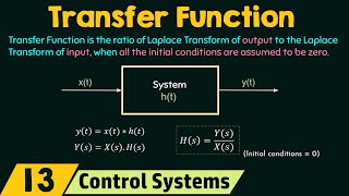
Transfer Function of an RLC Circuit
Enroll to start learning
You’ve not yet enrolled in this course. Please enroll for free to listen to audio lessons, classroom podcasts and take practice test.
Interactive Audio Lesson
Listen to a student-teacher conversation explaining the topic in a relatable way.
Introduction to RLC Circuit Components
🔒 Unlock Audio Lesson
Sign up and enroll to listen to this audio lesson

Today, we're diving into the series RLC circuit. Who can tell me what components make up this circuit?

It has a resistor, an inductor, and a capacitor.
Exactly! Each of these components plays a crucial role. Can anyone explain the function of the resistor?

The resistor opposes current flow and converts electrical energy into heat.
Great answer! Now, the inductor and capacitor store energy, but in different forms. Can someone explain how?

The inductor stores energy in a magnetic field, while the capacitor stores it in an electric field.
That's right! Remember this with the mnemonic **'MICE'**: *'Magnetic Inductor, Capacitor Electric.'* Let's summarize: the resistor dissipates energy, the inductor stores in a magnetic field, and the capacitor stores in an electric field.
Voltage-Current Relationships
🔒 Unlock Audio Lesson
Sign up and enroll to listen to this audio lesson

We have our components; next, let's look at the voltage-current relationships. What do we know about the voltage across the resistor?

It follows Ohm's Law, so V_R = I R.
Correct! Now how about the inductor?
It's V_L = L(dI/dt).
That's right! Now let's talk about the capacitor. Who can tell me its formula?
It's V_C = (1/C) ∫ I dt.
Exactly! Remember: for the capacitor, think of it as integrating current to find voltage. Let's recap these relationships: Resistor – *Ohm's Law*; Inductor – *rate of change of current*; Capacitor – *integral of current*.
Summation of Voltages
🔒 Unlock Audio Lesson
Sign up and enroll to listen to this audio lesson
Now, we need to sum the individual voltages to find the total in the circuit. Can someone express this mathematically?
V_in(t) = V_R + V_L + V_C.
Yes! And can you expand this using our earlier voltage equations?
So, V_in(t) = IR + L(dI/dt) + (1/C) ∫ I dt.
Great job! Summarizing here makes sure we remember how each component contributes to the total voltage in the RLC circuit.
Laplace Transform and Simplification
🔒 Unlock Audio Lesson
Sign up and enroll to listen to this audio lesson
Next, we will apply the Laplace transform to our voltage equation. What does the Laplace of V_in(t) look like?
V_in(s) = I(s) R + I(s) L s + (I(s) / (C s)).
That's correct! Can someone tell me what we do next?
We factor out I(s). So, V_in(s) = I(s)(R + Ls + (1/C) s).
Exactly! This is a big step towards finding the transfer function. Let's remember: factoring helps simplify our equations.
Deriving the Transfer Function
🔒 Unlock Audio Lesson
Sign up and enroll to listen to this audio lesson
Finally, let's derive the transfer function. What do we call the ratio of output current to input voltage?
That's the transfer function H(s).
Right! So what is H(s) for our RLC circuit?
H(s) = I(s) / V_in(s) = 1 / (R + Ls + (1/C s)).
Excellent! This transfer function expresses the relationship between output and input, crucial for analyzing control systems. Always remember: **'Relationship from Output to Input!'** Let's summarize our journey in this section.
Introduction & Overview
Read summaries of the section's main ideas at different levels of detail.
Quick Overview
Standard
In this section, we explore the series RLC circuit consisting of resistors, inductors, and capacitors in series. We describe the voltage-current relationship for the components and derive the transfer function, which represents the output current in relation to the input voltage. Understanding this derivation is crucial for analyzing electrical systems in control engineering.
Detailed
Transfer Function of an RLC Circuit
This section examines the series RLC circuit comprising a resistor (R), an inductor (L), and a capacitor (C) aligned in series. Understanding the transfer function for this circuit is vital in control systems and electrical engineering.
System Description
- Components of the circuit:
- Resistor (R): Opposes the current flow, dissipating energy as heat.
- Inductor (L): Stores energy in a magnetic field when current flows through it.
- Capacitor (C): Stores energy in an electric field when voltage is applied across it.
Voltage-Current Relationships
The individual voltage across each component is described by:
- Resistor: V_R = I R (Ohm's Law)
- Inductor: V_L = L(dI/dt)
- Capacitor: V_C = (1/C) ∫ I dt
Summation of Voltages
The sum of these voltages equals the input voltage:
V_in(t) = V_R + V_L + V_C = I R + L(dI/dt) + (1/C) ∫ I dt
Deriving the Laplace Transform
Taking the Laplace transform of the equation results in:
V_in(s) = I(s) R + I(s) L s + I(s) (1 / C s)
Factoring out I(s) gives:
V_in(s) = I(s) (R + L s + (1/C) s)
Transfer Function
The transfer function H(s) is defined as the ratio of the output current I(s) to the input voltage V_in(s):
H(s) = I(s) / V_in(s) = 1 / (R + Ls + (1/(C s)))
This transfer function expresses the relationship between the output current and input voltage, essential for analyzing a linear time-invariant (LTI) system.
Youtube Videos


Audio Book
Dive deep into the subject with an immersive audiobook experience.
System Description of the RLC Circuit
Chapter 1 of 6
🔒 Unlock Audio Chapter
Sign up and enroll to access the full audio experience
Chapter Content
Next, let’s look at an example from electrical engineering: the series RLC circuit, which consists of a resistor RR, an inductor LL, and a capacitor CC connected in series.
System Description:
● Resistor (R): Resists the flow of current.
● Inductor (L): Stores energy in the form of a magnetic field.
● Capacitor (C): Stores energy in the form of an electric field.
Detailed Explanation
In this chunk, we introduce the series RLC circuit, which is a fundamental electrical circuit made of three components: resistor (R), inductor (L), and capacitor (C). The resistor opposes electrical current, the inductor stores energy as a magnetic field when current flows through it, and the capacitor stores energy as an electric field when it is charged. These components work together to determine the circuit's behavior in response to electrical signals.
Examples & Analogies
Think of an RLC circuit like a water system: the resistor is like a narrow pipe that slows down water flow (like the resistor slowing down current), the inductor is like a water reservoir that temporarily holds water (storing energy like a magnetic field), and the capacitor is like a balloon that expands when water is added and contracts when it is removed (storing energy in an electric field).
Voltage-Current Relationships
Chapter 2 of 6
🔒 Unlock Audio Chapter
Sign up and enroll to access the full audio experience
Chapter Content
Voltage-Current Relationship:
The voltage across each component in the circuit can be described by:
● Resistor: VR=IR
● Inductor: VL=LdIdt
● Capacitor: VC=1C∫Idt
Detailed Explanation
Here, we delve into how the voltage relates to the current flowing through each component of the RLC circuit. For the resistor, voltage (VR) equals current (I) multiplied by resistance (R). For the inductor, the voltage (VL) is equal to inductance (L) times the rate of change of current with respect to time. Lastly, for the capacitor, the voltage (VC) is the integral of current over time, scaled by the capacitance (C). These relationships are crucial for analyzing and understanding circuit behavior.
Examples & Analogies
Imagine a traffic system: the resistor is like a traffic light that slows down cars (resistance), the inductor is like a ramp that stores cars in a queue (voltage based on changing flow), and the capacitor is comparable to a parking lot where cars can stay for a while (storing electric charge until it's released). The voltage across each part depends on how many cars (current) are flowing at any point in time.
Input Voltage and Component Voltage Summation
Chapter 3 of 6
🔒 Unlock Audio Chapter
Sign up and enroll to access the full audio experience
Chapter Content
The sum of the voltages around the circuit is equal to the input voltage:
Vin(t)=VR+VL+VC=IR+LdIdt+1C∫Idt
Detailed Explanation
This chunk discusses Kirchhoff's Voltage Law, which states that the sum of voltages around any closed loop in a circuit must equal zero. In this case, the total input voltage (Vin) must equal the sum of the voltages across the resistor (VR), inductor (VL), and capacitor (VC). This relationship sets the foundation for developing a differential equation that describes the dynamic behavior of the RLC circuit.
Examples & Analogies
Similar to how in a balanced budget all expenses must equal income, in an electrical circuit, the total voltage supplied must balance with the voltage drops across each component. If more voltage comes in than is used, it causes problems; just like in a financial budget.
Taking the Laplace Transform
Chapter 4 of 6
🔒 Unlock Audio Chapter
Sign up and enroll to access the full audio experience
Chapter Content
Taking the Laplace transform of the equation:
Vin(s)=I(s)R+I(s)Ls+I(s)1Cs
Detailed Explanation
In this step, we transform the time domain equations into the frequency domain using the Laplace transform, which is particularly useful for solving differential equations. Here, we express the input voltage as a function of the Laplace-transformed current (I(s)) and the circuit components. This transformation facilitates the analysis of the system's response to various inputs, as it allows us to work with algebraic equations rather than differential equations.
Examples & Analogies
Think of it like translating a recipe from a local language into a universal culinary language. Once translated, it's easier for chefs (engineers) around the world to understand and replicate the dish (circuit behavior) without needing to know the specifics of the local language (time-domain equations).
Factoring Out Current
Chapter 5 of 6
🔒 Unlock Audio Chapter
Sign up and enroll to access the full audio experience
Chapter Content
Factoring out I(s):
Vin(s)=I(s)(R+Ls+1Cs)
Detailed Explanation
Here, we rearrange the equation to isolate the current variable I(s). By factoring it out, we simplify the relationship between the input voltage and other parameters of the circuit. This makes it easier to analyze how the input affects the current flowing in the circuit, a key aspect in control system design.
Examples & Analogies
Imagine how a teacher might summarize a class assignment by grouping all similar tasks together. By focusing on the core elements (like current), we can streamline the process of understanding what needs to be done and how different factors interact, rather than getting lost in the details of each individual task.
Defining the Transfer Function
Chapter 6 of 6
🔒 Unlock Audio Chapter
Sign up and enroll to access the full audio experience
Chapter Content
The transfer function H(s) is the ratio of the output (current I(s)) to the input voltage Vin(s):
H(s)=I(s)Vin(s)=1R+Ls+1Cs
Detailed Explanation
Finally, we define the transfer function H(s) for the RLC circuit, which describes how the output current (I(s)) relates to the input voltage (Vin(s)). This transfer function encapsulates the entire dynamic behavior of the circuit's response to input signals and is crucial for understanding the stability and performance of the circuit.
Examples & Analogies
The transfer function is akin to a recipe that explains how to convert specific ingredients (input voltage) into a finished dish (current output). Just as a good recipe dictates how the ingredients interact to create a delicious meal, the transfer function tells us how the components in an RLC circuit interact to produce the desired electrical output.
Key Concepts
-
RLC Circuit: A circuit made up of a resistor, inductor, and capacitor connected in series, which is useful for studying electrical dynamics.
-
Transfer Function: Represents the relation between the output (current) and input (voltage) in the Laplace domain for a circuit or system.
-
Voltage-Current Relationship: The equations that describe how voltage relates to current in each component of the RLC circuit.
Examples & Applications
In a series RLC circuit with R = 2Ω, L = 1H, and C = 0.5F, we can calculate the transfer function to understand how the circuit responds to different input voltages.
If an input voltage of 10V is applied to an RLC circuit, understanding the transfer function allows an engineer to predict the output current and analyze the system dynamics.
Memory Aids
Interactive tools to help you remember key concepts
Rhymes
When you add voltages, don't forget to see, The resistor, inductor, and capacitor agree!
Stories
Imagine a circuit party where R, L, and C are dancing. R is resisting the urge to get hot-headed while L is storing energy, creating magnetic excitement, and C is capturing electric vibes!
Memory Tools
Remember RLC: 'Resistors Lower Current' to recall how they resist current flow.
Acronyms
The 'RLC' helps us remember
*R*esistor
*L*ductor
*C*apacitor.
Flash Cards
Glossary
- RLC Circuit
A circuit consisting of a resistor (R), an inductor (L), and a capacitor (C) connected in series.
- Transfer Function
A mathematical representation that relates the output of a system to its input in the Laplace domain.
- Voltage
The electrical potential difference between two points in a circuit.
- Current
The flow of electric charge in a circuit.
- Laplace Transform
An integral transform that converts a function of time into a function of complex frequency.
Reference links
Supplementary resources to enhance your learning experience.