
Introduction to JFET
Interactive Audio Lesson
Listen to a student-teacher conversation explaining the topic in a relatable way.
Introduction to JFETs
🔒 Unlock Audio Lesson
Sign up and enroll to listen to this audio lesson

Today, we'll be diving into the world of Junction Field Effect Transistors, or JFETs for short. Can anyone tell me what distinguishes a JFET from other types of transistors?

Are JFETs different because they are voltage-controlled?
Exactly! JFETs are indeed voltage-controlled devices. This is a fundamental difference from BJTs, which are current-controlled. Remember the acronym VV for 'Voltage-controlled vs. Current-controlled.'

So, what is the role of the gate in a JFET?
Great question! The gate voltage controls the drain current, I_D, by creating a depletion region that regulates the flow of charge carriers. Let's hold this thought for our next session.
Charge Carriers in JFETs
🔒 Unlock Audio Lesson
Sign up and enroll to listen to this audio lesson

Now, let’s discuss the types of charge carriers in JFETs. Can someone explain what they are?

I think n-channel JFETs use electrons and p-channel JFETs use holes.
Correct! The n-channel uses electrons, while the p-channel uses holes. This means JFETs operate unipolar, as opposed to BJTs that utilize both electrons and holes. Remember: Unipolar means one type of carrier!

Does that make JFETs simpler to manage than BJTs?
In many ways, yes. Simplicity in terms of control and applications is one of the JFET's strong suits.
Applications of JFETs
🔒 Unlock Audio Lesson
Sign up and enroll to listen to this audio lesson
Now, let’s shift our focus to where JFETs are used. Who can name a few applications?
I know they are used in amplifiers!
That's right! JFETs are widely used for small-signal amplification due to their high input impedance. Who can tell me why high input impedance is beneficial?
It allows them to not load down the input signal!
Exactly! This characteristic makes them ideal for many applications, including analog switches and voltage-controlled resistors. Knowledge retention tip: Think of JFET - 'Just For Excellent Transistor use!'
Introduction & Overview
Read summaries of the section's main ideas at different levels of detail.
Quick Overview
Standard
JFETs utilize voltage rather than current to control the flow of charge carriers, demonstrating unique characteristics such as high input impedance and low noise. They operate with only one type of charge carrier, making them distinct from bipolar junction transistors (BJTs).
Detailed
Introduction to JFET
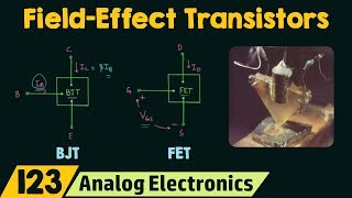
The Junction Field Effect Transistor (JFET) is a vital electronic component that serves as a voltage-controlled unipolar device for amplifying or switching signals. Unlike bipolar junction transistors (BJTs), which operate through current control, JFETs rely on voltage applied to the gate to regulate the drain current (I_D). One of the defining features of JFETs is their operation using a single type of charge carrier, specifically electrons in n-channel and holes in p-channel configurations.
Key Points:
- Voltage Control: JFETs use gate voltage to control the drain current, making them advantageous for various applications in electronic circuits.
- Unipolar Device: They utilize either electrons or holes as charge carriers, contrasting with the bipolar operation of BJTs.
- Applications: JFETs are commonly used in amplifiers, analog switches, and voltage-controlled resistors due to their high input impedance and low power consumption.
This section sets the foundation for understanding the subsequent construction, operating principles, and applications of JFETs.
Youtube Videos
![Junction Field Effect Transistor [JFET] Explained: Construction, Working, Application | Shubham Kola](https://img.youtube.com/vi/aJkwU7zLC70/mqdefault.jpg)
Audio Book
Dive deep into the subject with an immersive audiobook experience.
What is a JFET?
Chapter 1 of 2
🔒 Unlock Audio Chapter
Sign up and enroll to access the full audio experience
Chapter Content
A Junction Field Effect Transistor (JFET) is a voltage-controlled unipolar device used for amplifying or switching signals.
Detailed Explanation
A JFET, or Junction Field Effect Transistor, is specially designed to control current flow using voltage. This unique feature allows it to amplify signals, which is essential in many electronic devices. Unlike BJTs (Bipolar Junction Transistors), which rely on current to control output, JFETs are voltage-controlled devices, making them more energy-efficient in specific applications.
Examples & Analogies
Imagine a water faucet that is controlled by turning a knob instead of pushing a lever. In this analogy, the flow of water represents the electrical current, the knob represents the voltage control, and turning it adjusts how much water comes out, similar to how a JFET adjusts electrical signals.
Key Characteristics of JFETs
Chapter 2 of 2
🔒 Unlock Audio Chapter
Sign up and enroll to access the full audio experience
Chapter Content
Unlike BJTs (which are current-controlled), JFETs use voltage applied to the gate to control the drain current (I_D). It operates using only one type of charge carrier (electrons in n-channel, holes in p-channel).
Detailed Explanation
In a JFET, the operation is based on controlling the flow of current through a semiconductor channel by changing the voltage at the gate terminal. This gate is crucial, as it uses the principle of depletion regions, where access to the channel is limited by the applied voltage. JFETs come in two varieties: n-channel and p-channel, where n-channel uses electrons as charge carriers, and p-channel uses holes.
Examples & Analogies
Think of the JFET as a slide at a playground where children (charge carriers) can go down. The gate acts like a parent controlling how many children can go down the slide at once by allowing or restricting entrance based on how loud they shout (voltage applied). In an n-channel JFET, shouting louder (applying a higher voltage) allows more children (electrons) to come down, whereas in a p-channel, it may involve a different dynamic, like allowing only those who are quiet enough (having positive values) to go down.
Key Concepts
-
Junction Field Effect Transistor (JFET): A type of transistor that is voltage-controlled and operates with a single type of charge carrier.
-
Drain Current (I_D): The current that flows from the drain terminal, controlled through the gate voltage.
-
Unipolar Operation: JFETs operate with either holes or electrons, making them unipolar devices.
Examples & Applications
An n-channel JFET, commonly used in amplifier circuits, controls the drain current based on the gate voltage applied, minimizing interference from other circuit components.
A p-channel JFET might be used in an analog switch, offering voltage-controlled behavior to selectively allow current flow.
Memory Aids
Interactive tools to help you remember key concepts
Rhymes
JFET is cool, it's voltage controlled, no need for a current to uphold!
Stories
Imagine a security gate. The gate (JFET) only opens when you show a specific voltage card. If you show current, the gate stays closed. This illustrates how JFETs work with gate voltage, not current.
Memory Tools
Remember: JFET = Just Fixing Electronic Trouble.
Acronyms
JFET
Junction For Efficient Transistor usage.
Flash Cards
Glossary
- JFET
Junction Field Effect Transistor; a voltage-controlled unipolar device used for amplifying or switching signals.
- Drain Current (I_D)
The current flowing through the drain terminal of a JFET, controlled by the gate voltage.
- Unipolar Device
A device that utilizes only one type of charge carrier, either electrons or holes.
- Gate Voltage
The voltage applied to the gate terminal of a JFET, regulating the drain current.
Reference links
Supplementary resources to enhance your learning experience.