
Summary of Key Concepts
Interactive Audio Lesson
Listen to a student-teacher conversation explaining the topic in a relatable way.
Introduction to JFET Functionality
🔒 Unlock Audio Lesson
Sign up and enroll to listen to this audio lesson

Welcome class! Today, we're diving into the Junction Field Effect Transistor. Can anyone tell me what a JFET is?

Isn't it a type of transistor?
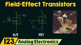
That's correct! A JFET is a voltage-controlled unipolar device used for amplifying or switching signals. It’s different from BJTs, which are current-controlled. Remember, JFETs use voltage applied to the gate to control the drain current, denoted as I_D.

So it only uses one type of charge carrier?
Exactly! In n-channel JFETs, we have electrons, while in p-channel JFETs, we have holes. Let’s keep this in mind as we proceed.
In summary, JFET stands for Junction Field Effect Transistor; it operates primarily through voltage control.
Operating Regions of JFET
🔒 Unlock Audio Lesson
Sign up and enroll to listen to this audio lesson

Now that we’ve covered the basics of JFET, let’s talk about its operating regions. Who can name them?

There is the Ohmic region, right?
Yes! The Ohmic region is where the JFET acts like a variable resistor. What about the Active region?

That’s where it amplifies the signal!
Correct! Lastly, we have the Cut-off region, where the channel is closed and almost no current flows.
To remember these regions, think of 'Ohmic, Active, Cut-off' or just OAC. Can you all remember that?
Characteristics and Control Mechanism
🔒 Unlock Audio Lesson
Sign up and enroll to listen to this audio lesson
Let’s delve into how the gate voltage controls current flow. What happens as the gate-source voltage becomes more negative?
The depletion region becomes wider, right?
Exactly! This narrowing of the channel affects how much current can flow. Beyond a certain point, known as the pinch-off voltage, increasing voltage doesn’t significantly increase the drain current I_D.
So, the JFET can quickly switch between its operating regions?
Precisely! This flexibility makes the JFET suitable for various applications, especially where high input impedance and low noise are required.
To summarize, gate voltage not only controls the conductance of the JFET through the depletion region but also helps in maintaining performance across different operational regions.
Introduction & Overview
Read summaries of the section's main ideas at different levels of detail.
Quick Overview
Standard
JFETs utilize voltage at the gate to control current through a reverse-biased depletion region, providing high input impedance and low noise, which is beneficial for signal processing applications.
Detailed
In this section, we summarize the key concepts surrounding the Junction Field Effect Transistor (JFET). As a voltage-controlled unipolar device, the JFET integrates functionality to amplify or switch signals effectively. It operates through three primary regions: Ohmic, where it behaves like a variable resistor; Active, where it amplifies signals; and Cut-off, where no current flows. The unique control mechanism at play involves the gate voltage affecting the drain current by influencing the depletion region width at the gate-source junction. Overall, the JFET stands out due to its high input impedance and low noise characteristics, making it an integral part of various signal processing applications.
Youtube Videos
![Junction Field Effect Transistor [JFET] Explained: Construction, Working, Application | Shubham Kola](https://img.youtube.com/vi/aJkwU7zLC70/mqdefault.jpg)
Audio Book
Dive deep into the subject with an immersive audiobook experience.
Overview of JFET
Chapter 1 of 4
🔒 Unlock Audio Chapter
Sign up and enroll to access the full audio experience
Chapter Content
● JFET is a voltage-controlled, unipolar device.
Detailed Explanation
A Junction Field Effect Transistor, or JFET, is a type of transistor that is controlled by voltage rather than current. This means that it can amplify or switch electronic signals by varying the voltage applied to its gate terminal. The term 'unipolar' indicates that it primarily uses one type of charge carrier, either electrons or holes, unlike bipolar devices like BJTs that use both.
Examples & Analogies
Think of a JFET like a water tap that controls the flow of water (current) based on how much the tap is turned (gate voltage). When you twist the tap to open it slightly (applying a small voltage), a tiny stream of water flows out. If you turn it more (increase the voltage), the flow increases accordingly.
Operating Regions of JFET
Chapter 2 of 4
🔒 Unlock Audio Chapter
Sign up and enroll to access the full audio experience
Chapter Content
● Operates in three regions: Ohmic, Active, and Cut-off.
Detailed Explanation
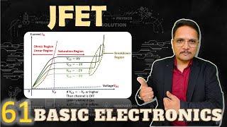
The JFET works in three distinct operating regions. In the Ohmic region, the device behaves like a variable resistor where the current varies linearly with voltage. During the Active region, it acts as an amplifier, maintaining a constant drain current despite changes in voltage, as long as it remains below the pinch-off voltage. In the Cut-off region, the gate voltage is too low to allow any current to flow, effectively turning the transistor off.
Examples & Analogies
Imagine a sliding door as the JFET. When you slide it open a little (Ohmic), you can see through (small current flows). If you slide it open halfway (Active), it’s fully engaged but allows you to pass through easily (constant current). If you push it completely closed (Cut-off), no one can go through – it’s effectively shut down.
Current Control Mechanism
Chapter 3 of 4
🔒 Unlock Audio Chapter
Sign up and enroll to access the full audio experience
Chapter Content
● Gate voltage controls current through the reverse-biased depletion region.
Detailed Explanation
In a JFET, the gate is reverse-biased, meaning a negative voltage is applied that widens the depletion region (where charge carriers cannot exist). This depletion region effectively narrows the channel through which current flows. By adjusting the gate voltage, you can control how much of the channel is available for current flow, hence regulating the overall current through the JFET.
Examples & Analogies
Imagine the JFET as a narrow path in a park that can be blocked off. The gate voltage is like a fence being built across the path. The higher the fence (more negative voltage), the less available path there is for people to walk through (current flow). When the fence is low, more people can walk through—more current can flow.
Benefits of JFETs
Chapter 4 of 4
🔒 Unlock Audio Chapter
Sign up and enroll to access the full audio experience
Chapter Content
● It offers high input impedance and low noise, making it ideal for signal processing applications.
Detailed Explanation
One of the significant advantages of JFETs is their high input impedance, which means they draw very little current from the input signal source. This feature makes them highly suitable for applications like amplifiers where preserving the integrity of the input signal is crucial. Additionally, their low noise levels make them ideal for sensitive signal processing tasks, such as in audio equipment.
Examples & Analogies
Think of using a microphone that is very sensitive to sound. If it has high input impedance, it won't pick up any unwanted noise, ensuring your voice is clear and distinct, similar to how JFETs work in amplifying sound without adding noise.
Key Concepts
-
Voltage-controlled: JFETs use voltage applied to the gate to control current.
-
Operating regions: JFETs have three operating regions: Ohmic, Active, and Cut-off.
-
Depletion region: Narrowing of the channel affects current flow significantly.
Examples & Applications
An n-channel JFET operates with electrons as charge carriers, making it efficient for high-frequency applications.
A p-channel JFET can be utilized where positive charge carriers are preferred, such as in specific analog applications.
Memory Aids
Interactive tools to help you remember key concepts
Rhymes
JFETs control with voltage, you'll see, ohmic is where current flows free.
Stories
Imagine a gate that controls many cars in a parking lot. The more gates close, the fewer cars (or current) can leave until all gates lead to a single exit (pinch-off).
Memory Tools
Remember OAC for the operating regions of JFET: Ohmic, Active, and Cut-off.
Acronyms
JFC
JFET - For Voltage Control!
Flash Cards
Glossary
- JFET
Junction Field Effect Transistor, a voltage-controlled unipolar device.
- Voltagecontrolled
A type of control mechanism where the output current is regulated by voltage.
- Depletion region
The area in a semiconductor where charge carriers are depleted, affecting current flow.
- Pinchoff voltage
The voltage at which the channel width becomes so narrow that current saturates.
Reference links
Supplementary resources to enhance your learning experience.