
JFET Characteristics
Interactive Audio Lesson
Listen to a student-teacher conversation explaining the topic in a relatable way.
Output Characteristics of JFET
🔒 Unlock Audio Lesson
Sign up and enroll to listen to this audio lesson

Let's dive into the output characteristics of the JFET! What do you think happens to the drain current when we vary the drain-source voltage?

I guess it increases with V_DS until a point?
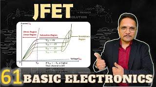
Exactly! This leads us to the Ohmic region, where the device behaves like a variable resistor. If V_DS is small, you can see a linear relationship. What happens after this region?

It enters the Saturation region, right?
Correct! In the Saturation region, after a certain V_DS, the current stabilizes and doesn't increase further. This is crucial for amplification. Can someone remind me what this region is called when the current stabilizes?

That's the Saturation region!
Well done! Now, what's the last region we discuss?

The Cutoff region!
Absolutely! This is when the gate-source voltage reaches the cutoff voltage, and the current approaches zero. It’s important to remember that it’s analogous to putting the device in an OFF state.
To summarize, output characteristics highlight crucial regions: Ohmic, Saturation, and Cutoff, which assist in understanding how a JFET functions.
Transfer Characteristics of JFET
🔒 Unlock Audio Lesson
Sign up and enroll to listen to this audio lesson

Now, let's shift our focus to Transfer Characteristics. Who can explain what it means to relate I_D with V_GS?
I'm guessing it's how the drain current changes when we adjust the gate voltage?
Correct! This relationship is expressed by Shockley’s Equation. Can anyone recall the form of that equation?
It's I_D = I_DSS * (1 - V_GS / V_GS(off))², right?
Perfect! Now, who can identify what each term represents?
I_D is the drain current, I_DSS is the max current when V_GS is zero, and V_GS(off) is the cutoff voltage.
Exactly! As V_GS approaches V_GS(off), the drain current decreases to zero. Can anyone summarize why understanding these characteristics is important?
It helps in designing circuits that utilize JFETs for different applications like amplifiers!
Well said! To wrap up, transfer characteristics are essential in determining how JFET responds to changes in gate voltage, critical for circuit design.
Introduction & Overview
Read summaries of the section's main ideas at different levels of detail.
Quick Overview
Standard
This section focuses on the output and transfer characteristics of Junction Field Effect Transistors (JFETs), elaborating on the distinct regions of operation, the governing equations, and the significance of parameters like drain current in relation to gate-source voltage.
Detailed
JFET Characteristics
JFET (Junction Field Effect Transistor) characteristics include both the output and transfer characteristics of the device.
- Output Characteristics: This part graphically represents the relationship between the drain current (I_D) and the drain-source voltage (V_DS) for constant gate-source voltage (V_GS). The curve showcases three distinct operational regions:
- Ohmic Region: Where V_DS is small, and the JFET behaves like a variable resistor.
- Saturation Region: Occurs when V_DS exceeds the threshold relative to V_GS and pinch-off voltage (V_P), leading to a constant drain current (I_D), ideal for amplification.
- Cutoff Region: Defined by the cutoff voltage (V_GS(off)), where the channel is closed, and I_D approaches zero.
- Transfer Characteristics: These characteristics are determined by Shockley's Equation:
ID = IDSS(1 − VGS / VGS(off))²
Here,
- I_D: Drain current
- I_DSS: Maximum drain current when V_GS = 0
- V_GS(off): The gate-source cutoff voltage where I_D = 0.
Understanding these characteristics is crucial for designing circuits that utilize JFETs for amplification and switching.
Youtube Videos

![Junction Field Effect Transistor [JFET] Explained: Construction, Working, Application | Shubham Kola](https://img.youtube.com/vi/aJkwU7zLC70/mqdefault.jpg)
Audio Book
Dive deep into the subject with an immersive audiobook experience.
Output Characteristics of JFET
Chapter 1 of 2
🔒 Unlock Audio Chapter
Sign up and enroll to access the full audio experience
Chapter Content
- Output Characteristics (I_D vs V_DS for constant V_GS):
● Shows three distinct regions: Ohmic, Saturation, and Cutoff.
Detailed Explanation
The output characteristics of a JFET describe how the drain current (I_D) varies with the drain-source voltage (V_DS) under constant gate-source voltage (V_GS).
1. Ohmic Region: Here, the JFET behaves like a variable resistor. The current increases linearly with an increase in V_DS. This is because the channel is wide enough, allowing more carriers to pass.
2. Saturation Region: In this region, increasing V_DS does not significantly increase I_D. This happens when the channel is constricted enough that it limits the current, leading the JFET to act as an amplifier.
3. Cutoff Region: Finally, in this region, the gate voltage (V_GS) is such that the channel is effectively closed, resulting in I_D being approximately zero. This means no current flows through the device.
Examples & Analogies
Think of a water hose. When the valve is open just a little (Ohmic), water flows through smoothly. As you close the valve (Saturation), water flow starts to steady and doesn’t increase much regardless of how much you crank the valve closed. At some point, if you completely close the valve (Cutoff), no water flows at all.
Transfer Characteristics of JFET
Chapter 2 of 2
🔒 Unlock Audio Chapter
Sign up and enroll to access the full audio experience
Chapter Content
- Transfer Characteristics (I_D vs V_GS):
● Governed by Shockley’s Equation:
ID=IDSS(1−VGSVGS(off))2I_D = I_{DSS} \left(1 - \frac{V_{GS}}{V_{GS(off)}} \right)^2
Where:
● IDI_D: Drain current
● IDSSI_{DSS}: Maximum drain current when VGS=0V_{GS} = 0
● VGS(off)V_{GS(off)}: Gate-source cut-off voltage (where ID=0I_D = 0)
Detailed Explanation
The transfer characteristics of a JFET show how the drain current (I_D) changes with varying gate-source voltage (V_GS). This relationship is quantitatively described by Shockley’s Equation, which illustrates that:
- I_D depends on the maximum current (I_DSS), which is the drain current when V_GS is 0.
- As V_GS becomes more negative (for an n-channel JFET), the current decreases. The steepness of this curve indicates how efficiently the JFET can respond to changes in voltage, illustrating the control that gate voltage has over the drain current.
Examples & Analogies
Imagine controlling the speed of a fan with a remote. When you press the button to increase the speed (increase V_GS), the airflow (I_D) increases to a maximum point. If you push the button too far in one direction (negative gate voltage), the fan slows down until it stops completely (cutoff). This analogy shows how JFETs control current flow through voltage manipulation.
Key Concepts
-
Output Characteristics: The relationship between drain current and drain-source voltage, showing distinct operational regions.
-
Transfer Characteristics: The correlation between drain current and gate-source voltage, defined by Shockley's Equation.
-
Ohmic Region: The range of small V_DS where the JFET operates as a variable resistor.
-
Saturation Region: The operational zone where drain current stabilizes and supports amplification.
-
Cutoff Region: The state where I_D is nearly zero, indicating that the JFET is off.
Examples & Applications
When a JFET is operated in the Ohmic region, it behaves like a variable resistor, making it suitable for applications requiring precise control of current.
In the Saturation region, a JFET can amplify signals efficiently, making it a preferred choice for audio amplification in circuits.
Memory Aids
Interactive tools to help you remember key concepts
Rhymes
In the Ohmic region, the flow is neat, / Like a variable resistor, it can’t be beat.
Stories
Imagine a JFET as a water faucet. In the Ohmic region, the water flows freely, like when you turn the faucet a little. As you turn it more (Saturation), the flow stabilizes despite how much you turn the faucet. If you turn it too far, the water stops (Cutoff).
Memory Tools
O for Ohmic, S for Saturation, C for Cutoff – Remember OSC for JFET regions!
Acronyms
For Transfer characteristics, remember ISD
I_D
I_DSS
V_GS(off) to recall the formula.
Flash Cards
Glossary
- Output Characteristics
The graphical representation of the relationship between the drain current (I_D) and the drain-source voltage (V_DS) while keeping gate-source voltage (V_GS) constant.
- Transfer Characteristics
The relationship between drain current (I_D) and gate-source voltage (V_GS), typically described by Shockley’s Equation.
- Ohmic Region
The operating region of a JFET where it behaves like a variable resistor when V_DS is small.
- Saturation Region
The region where, beyond a certain V_DS, the drain current remains constant and the JFET is used for amplification.
- Cutoff Region
The operating region when the gate-source voltage reaches the cutoff voltage, effectively turning off the JFET.
- Shockley’s Equation
An equation that defines the transfer characteristics of a JFET, linking drain current to gate-source voltage.
Reference links
Supplementary resources to enhance your learning experience.