
Junction Field Effect Transistors (JFETs)
Interactive Audio Lesson
Listen to a student-teacher conversation explaining the topic in a relatable way.
Introduction to JFET
🔒 Unlock Audio Lesson
Sign up and enroll to listen to this audio lesson

Today, we're discussing Junction Field Effect Transistors, or JFETs. Can anyone tell me what makes JFETs different from BJTs?

JFETs are voltage-controlled devices, while BJTs are current-controlled.
Exactly! JFETs use voltage applied to the gate to control the drain current. What do you think is the significance of being a unipolar device?

Could it mean they're simpler to operate since they only use one type of charge carrier?
Right again! In JFETs, we primarily have electrons in n-channel and holes in p-channel. Let's remember this with the acronym 'U-VC' for Unipolar-Voltage Controlled!
Construction of JFET
🔒 Unlock Audio Lesson
Sign up and enroll to listen to this audio lesson

Now, let’s look at construction. How many types of JFETs do we have?

There are n-channel and p-channel types!
Correct! The n-channel JFET consists of an n-type semiconductor bar with p-type gate regions. Can someone explain the terminal functions?

The source is where the carriers enter, the drain is where they exit, and the gate controls the channel width.
Well summarized! Remember, the source is 'Where it Starts', the drain is 'Where it Exits', and the gate is 'The Gatekeeper.'
Working Principle of JFET
🔒 Unlock Audio Lesson
Sign up and enroll to listen to this audio lesson
Let’s dive into the working principle of JFETs. What happens to the gate-source junction?
The gate-source junction is always reverse-biased.
Exactly, and as V_GS becomes negative, what's the effect on the depletion region?
The depletion region widens, reducing channel width!
Very good! Eventually, we reach a pinch-off voltage. Who remembers what that is?
It’s the point where drain current saturates because the channel is too narrow!
Correct! Let’s use the mnemonic 'W-PB' for Widening-Pinch-off to help us remember!
Operating Regions of JFET
🔒 Unlock Audio Lesson
Sign up and enroll to listen to this audio lesson
Now, can anyone explain the three operating regions of a JFET?
Uh, there's Ohmic, Saturation, and Cutoff!
Exactly! In the Ohmic region, what is the behavior of the JFET?
It acts like a variable resistor!
And in Saturation?
I_D is constant; it works as an amplifier!
Great! Finally, what happens in the Cutoff region?
The channel is closed and I_D is approximately zero!
Exactly, remember 'OSC' for Ohmic- Saturation-Cutoff to recall the regions!
Applications and Characteristics of JFET
🔒 Unlock Audio Lesson
Sign up and enroll to listen to this audio lesson
Can anyone share some applications for JFETs?
They are used in amplifiers!
And in analog switches!
Exactly! Their high input impedance is a major advantage. What about characteristics of JFETs?
We have output and transfer characteristics. Isn’t it governed by Shockley’s equation?
Spot on! And remember, each characteristic reflects how input affects output. Let’s summarize by saying 'J-FAP' - JFET Applications and Parameters!
Introduction & Overview
Read summaries of the section's main ideas at different levels of detail.
Quick Overview
Standard
JFETs operate using a single type of charge carrier and are categorized into n-channel and p-channel types. They utilize the voltage applied to the gate to modulate the drain current, with distinct operating regions including Ohmic, Saturation, and Cutoff.
Detailed
Junction Field Effect Transistors (JFETs)
Introduction
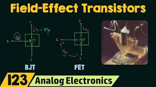
A Junction Field Effect Transistor (JFET) is a voltage-controlled unipolar device primarily utilized in amplifying or switching electronic signals. JFETs are distinguished from bipolar junction transistors (BJTs), which are current-controlled. JFETs operate using one type of charge carrier, specifically electrons in n-channel and holes in p-channel structures.
Construction
There are two main types of JFETs: n-channel, which is more commonly used, and p-channel. The n-channel JFET consists of an n-type semiconductor with p-type gate regions that control the flow of charge carriers via three terminals: the source (S), drain (D), and gate (G).
Working Principle
The gate-source junction in a JFET is always reverse-biased, leading to a depletion region that impacts the channel width. As the gate-source voltage (V_GS) becomes more negative, the depletion region widens, reducing the channel width until reaching a 'pinch-off voltage' (V_P), where the drain current (I_D) saturates.
Operating Regions
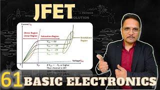
JFETs function in three primary operating regions:
1. Ohmic (Linear): JFET acts as a variable resistor.
2. Saturation (Active): Drain current remains constant; acts as an amplifier.
3. Cutoff: The channel is closed, and I_D approaches zero.
Characteristics and Parameters
Output characteristics demonstrate the relationship between drain current and drain-source voltage under various gate-source voltages. The transfer characteristics follow Shockley's equation, showing how I_D varies with V_GS. Important parameters include drain current (I_D), maximum drain current (I_DSS), and cutoff voltage (V_GS off).
Comparison with BJT
JFETs offer advantages over BJTs, such as higher input impedance and lower noise, making them preferable in certain applications. However, they also have disadvantages including limited gain and sensitivity to gate voltage.
Conclusion
Understanding JFETs and their parameters is crucial for applications in various electronic devices, particularly in amplification circuits due to their beneficial characteristics.
Youtube Videos
![Junction Field Effect Transistor [JFET] Explained: Construction, Working, Application | Shubham Kola](https://img.youtube.com/vi/aJkwU7zLC70/mqdefault.jpg)
Audio Book
Dive deep into the subject with an immersive audiobook experience.
Introduction to JFET
Chapter 1 of 4
🔒 Unlock Audio Chapter
Sign up and enroll to access the full audio experience
Chapter Content
A Junction Field Effect Transistor (JFET) is a voltage-controlled unipolar device used for amplifying or switching signals.
● Unlike BJTs (which are current-controlled), JFETs use voltage applied to the gate to control the drain current (I_D).
● It operates using only one type of charge carrier (electrons in n-channel, holes in p-channel).
Detailed Explanation
A JFET is a type of transistor that is controlled by voltage rather than current. Unlike bipolar junction transistors (BJTs), where the current flowing through the transistor controls its operation, JFETs utilize a gate voltage to regulate the flow of current from the source to the drain. This makes JFETs unipolar devices, operating with either electrons (in n-channel FETs) or holes (in p-channel FETs) as the charge carriers, leading to various applications in amplification and switching.
Examples & Analogies
Consider a water faucet as the JFET. When you turn the faucet (apply voltage), water (current) flows through the pipe (channel). The amount of water that flows depends on how far you turn the faucet. Just like how the JFET controls the current based on the voltage at the gate.
Types of JFET
Chapter 2 of 4
🔒 Unlock Audio Chapter
Sign up and enroll to access the full audio experience
Chapter Content
Two basic types:
1. n-channel JFET (more common)
2. p-channel JFET
n-channel JFET:
● Consists of an n-type semiconductor bar with p-type gate regions on either side.
● Terminals:
○ Source (S): Where carriers enter.
○ Drain (D): Where carriers exit.
○ Gate (G): Reverse-biased junction that controls the channel width.
Detailed Explanation
There are two primary types of JFETs: n-channel and p-channel. N-channel JFETs are more commonly used and are made from n-type material, where the charge carriers are electrons. The gate region consists of p-type material, creating a junction that controls how easily electrons can flow from the source to the drain. The essential parts of a JFET include the source (where current enters), the drain (where current exits), and the gate (which regulates the channel's size by being reverse-biased).
Examples & Analogies
Think of an n-channel JFET like a one-lane road (the channel) with entrances and exits (the source and drain). The gate acts like a traffic light that controls how many cars (electrons) can enter or exit. If the light is green (positive voltage), more cars can pass through; if it's red (negative voltage), the flow is restricted.
Working Principle of JFET
Chapter 3 of 4
🔒 Unlock Audio Chapter
Sign up and enroll to access the full audio experience
Chapter Content
● The gate-source junction is always reverse-biased.
● As V_GS becomes more negative (for n-channel), the depletion region widens, reducing the channel width.
● Eventually, at a certain pinch-off voltage (V_P), the channel is so narrow that drain current saturates.
● Beyond pinch-off, increasing V_DS doesn’t significantly increase I_D.
Detailed Explanation
The JFET operates on the principle of a reverse-biased gate-source junction. When a negative voltage is applied to the gate (in an n-channel), it creates a depletion region that expands, narrowing the path through which electrons can flow. When the voltage reaches a specific level known as the pinch-off voltage (V_P), the channel narrows to the point where further increases in voltage do not result in significantly more current through the drain (I_D), effectively saturating the device.
Examples & Analogies
Imagine a garden hose regulating water flow based on how much you squeeze it. Initially, squeezing the hose less allows water to flow easily, similar to how lowering the gate voltage allows more current. Once you squeeze it too tightly (reaching pinch-off), no matter how much more you try to squeeze, water flow (current) remains almost the same. This is similar to what happens when the JFET saturates.
JFET Biasing and Operating Regions
Chapter 4 of 4
🔒 Unlock Audio Chapter
Sign up and enroll to access the full audio experience
Chapter Content
Region Condition Behavior
Ohmic (Linear) V_DS small JFET acts like a variable resistor
Saturation (Active) V_DS > V_GS - V_P I_D is constant; JFET acts as amplifier
Cutoff V_GS ≤ V_GS(off) Channel closed; I_D ≈ 0
Detailed Explanation
JFETs operate in different regions depending on the voltages applied. In the Ohmic region, where V_DS (drain-source voltage) is small, the JFET behaves like a variable resistor, allowing for precise control. In the Saturation region, when V_DS exceeds the threshold set by the gate voltage minus pinch-off voltage, the device operates as an amplifier, maintaining a constant drain current. Finally, in the Cutoff region, if the gate voltage is below a certain level (V_GS(off)), the channel closes, and the drain current approximately equals zero, effectively turning off the JFET.
Examples & Analogies
Picture a dimmer switch for lights: when turned slightly (Ohmic region), the light brightness varies (acts like a variable resistor). When fully turned on (Saturation region), the light remains at a constant brightness (acts as an amplifier). Turning it to the lowest setting (Cutoff region) turns the light off completely.
Key Concepts
-
Voltage Control: JFETs are controlled by gate voltage rather than current.
-
Operating Regions: JFETs have multiple operating regions: Ohmic, Saturation, and Cutoff.
-
High Input Impedance: JFETs possess high input impedance, making them ideal for various applications.
Examples & Applications
An n-channel JFET is used in an audio amplifier, enabling high-quality sound without distortion due to its high input impedance.
A JFET can be utilized as an analog switch to control signals in a digital circuit.
Memory Aids
Interactive tools to help you remember key concepts
Rhymes
JFET acts like a gate, controlling where electrons skate.
Stories
Imagine a powerful gatekeeper in a city; the gate controls who enters and exits, just as the gate in a JFET controls the flow of current.
Memory Tools
Remember 'OhS-C' for Ohmic, Saturation, and Cutoff to recall JFET operating regions.
Acronyms
Use 'U-VC' to remember that JFET is Unipolar and Voltage-Controlled.
Flash Cards
Glossary
- Junction Field Effect Transistor (JFET)
A voltage-controlled unipolar device used for amplifying or switching signals, operating with either n-channel or p-channel structures.
- Drain Current (I_D)
The current flowing through the drain terminal of a JFET, controlled by the gate-source voltage.
- Pinchoff Voltage (V_P)
The gate-source voltage at which the JFET's channel narrows sufficiently to cause saturation of the drain current.
- Ohmic Region
The region of operation for a JFET where it behaves like a variable resistor.
- Saturation Region
The operating region where drain current remains constant, and the JFET acts as an amplifier.
- Cutoff Region
The region where the JFET is off, and the drain current is nearly zero.
Reference links
Supplementary resources to enhance your learning experience.