
Implementing Digital Systems on FPGAs
Interactive Audio Lesson
Listen to a student-teacher conversation explaining the topic in a relatable way.
Requirement Analysis
🔒 Unlock Audio Lesson
Sign up and enroll to listen to this audio lesson

Today, we will start by discussing the first phase of the FPGA design flow: Requirement Analysis. This stage is crucial because it determines what the final system needs to achieve. Can someone tell me why this step is important?

I think it’s important because if we don’t define what we need, we might end up implementing the wrong solution.
Exactly! Without a clear requirement, our design could go off course. We should always ask ourselves what functionalities we need, what performance metrics should be met, and the specifics of input/output. This is what I call the '3 F's: Functionality, Format, and Feasibility.' Can someone give an example of a requirement?

If we were making a counter, a requirement might be that it counts from zero to 15 and resets when a particular signal is received.
Great example! So, as we see, clearly described requirements guide the entire design process.
Design Entry
🔒 Unlock Audio Lesson
Sign up and enroll to listen to this audio lesson

The next step is Design Entry. This is where we write our design using VHDL or Verilog. Why do you think choosing the right HDL is crucial?

I think it matters because different HDLs might be better for different tasks or logic structures.
Yes! VHDL and Verilog have their strengths depending on the application. When entering the design, we use modules and entities to create a detailed map of our system. Remember the mnemonic 'M.A.D.' for Modules, Architecture, and Descriptions which highlights the key components we should be focusing on.

Can you provide a simple example of how a module looks in VHDL?
Certainly! A simple module might define an AND gate operation, which builds the groundwork for larger logic architectures.
Synthesis
🔒 Unlock Audio Lesson
Sign up and enroll to listen to this audio lesson
Now let’s discuss the Synthesis stage. When we synthesize our HDL code, what happens?
The HDL code gets converted into a gate-level netlist, right?
Precisely! This netlist shows how the logical connections are implemented using basic gates and flip-flops. It’s a crucial step as it translates our abstraction into something the FPGA can use. Can you all remember this as 'G.A.N.' - Gates, Architecture, and Netlist?
So, this is where we start to see our design come to life?
Absolutely! The netlist guides the next steps in the implementation process!
Implementation (Place and Route)
🔒 Unlock Audio Lesson
Sign up and enroll to listen to this audio lesson
The next phase is Implementation, focusing on Place and Route. This is where we optimize the mapping of our synthesized design onto the FPGA. What do you think we need to consider here?
I guess we have to think about the area and performance, like how efficient our design is.
Exactly! We want to ensure not only that it fits but that it performs optimally. Remember the acronym 'A.S.P.' which stands for Area, Speed, and Power. Can someone connect this to a real-world scenario?
I think of traffic management—if we have too many cars in one lane, it slows everything down. We need to balance the 'lanes' of our FPGA!
Fantastic analogy! Optimizing resources is akin to traffic management, ensuring everyone gets to where they need to go efficiently.
Testing and Debugging
🔒 Unlock Audio Lesson
Sign up and enroll to listen to this audio lesson
Finally, we reach Testing and Debugging. Why do we need to simulate our design before programming the FPGA?
To catch any errors or bugs in our logic before it's too late!
Correct! Simulations can reveal potential issues early on when fixes are much more manageable. We can use tools like ModelSim for this purpose. Remember the phrase 'C.A.N.'—Catch, Analyze, and Note—to keep in mind our approach during debugging. What's an example of a debugging tool?
There’s ChipScope for Xilinx, right?
Exactly! ChipScope would let us monitor internal signals in real time, ensuring our system runs smoothly.
Introduction & Overview
Read summaries of the section's main ideas at different levels of detail.
Quick Overview
Standard
The design flow for FPGAs encompasses several stages from requirement analysis to testing and debugging, covering essential tasks such as synthesis, implementation, and simulation. Understanding these steps is crucial for successfully deploying digital systems on FPGAs.
Detailed
Detailed Summary
Implementing Digital Systems on FPGAs
In this section, we delve into the FPGA design flow, which is vital for creating effective implementations of digital systems. The process consists of several sequential stages:
- Requirement Analysis: This initial stage focuses on defining the system's intended functionality, required performance metrics, and input-output specifications. Providing a clear guideline ensures that developers have a robust understanding of the objectives.
- Design Entry: Developers write the design using a hardware description language (HDL) such as VHDL or Verilog. This step is crucial as it involves articulating the logic and architecture of the system in detail, leveraging modules and entities.
- Synthesis: The HDL code is transformed into a gate-level netlist, which represents the correlation between different components like logic gates and flip-flops, enabling the subsequent design phases to accurately utilize the FPGA’s resources.
- Implementation (Place and Route): This phase maps the synthesized design onto the FPGA's programmable architecture. Here, considerations for resource optimization such as area, speed, and power efficiency come into play.
- Simulation and Verification: Before committing to hardware, simulation tools are utilized to validate the design's functionality. This step ensures that potential issues are identified and resolved early in the process, using tools like ModelSim.
- Programming the FPGA: Upon completing simulations, the design is compiled into a bitstream file that programs the FPGA, allowing it to operate according to specifications.
- Testing and Debugging: Finally, once the FPGA is programmed, thorough testing is conducted using debugging tools like logic analyzers to ensure the design performs correctly in the chosen environment.
Each stage of the design flow is critical for the successful deployment of digital systems on FPGAs, highlighting the intricacies involved in effective hardware design.
Youtube Videos

Audio Book
Dive deep into the subject with an immersive audiobook experience.
The FPGA Design Flow Overview
Chapter 1 of 8
🔒 Unlock Audio Chapter
Sign up and enroll to access the full audio experience
Chapter Content
The FPGA design flow consists of several stages, from initial specification to final programming. The key stages of the FPGA design flow are as follows:
Detailed Explanation
The FPGA design process is organized into a series of steps that guide the designer from the idea to the final product. First, you start with Requirement Analysis, where you define what the system needs to do. Next is Design Entry, where you write the design using a hardware description language (HDL) like VHDL or Verilog. The code is then synthesized into a netlist, representing the design in terms of basic logic components. After synthesis, you implement the design on the FPGA, optimizing it for efficient use of resources. Following implementation, you simulate and verify the design to ensure it behaves correctly before programming the FPGA and finally testing it with actual hardware.
Examples & Analogies
Think of the FPGA design flow like building a house. You first need to plan what type of house you want (Requirement Analysis), create blueprints (Design Entry), gather materials and construct the house (Synthesis and Implementation), ensure everything works as planned (Simulation), and finally move in and make it your home (Programming and Testing).
Requirement Analysis
Chapter 2 of 8
🔒 Unlock Audio Chapter
Sign up and enroll to access the full audio experience
Chapter Content
- Requirement Analysis
- Define the system’s functionality, input/output specifications, performance requirements, and constraints.
Detailed Explanation
In the Requirement Analysis step, the designer determines exactly what the FPGA-based system must achieve. This involves detailing the necessary functions the system needs to perform, identifying what inputs it will accept, and understanding the expected outputs. Furthermore, performance requirements—such as speed, efficiency, and response time—are established, along with any limitations or constraints that might affect the design.
Examples & Analogies
This is akin to planning a trip. You decide your destination (system functionality), what you will bring with you (inputs and outputs), how long the trip should take (performance requirements), and any limitations like budget or time constraints.
Design Entry
Chapter 3 of 8
🔒 Unlock Audio Chapter
Sign up and enroll to access the full audio experience
Chapter Content
- Design Entry
- Write the design in a hardware description language (HDL) like VHDL or Verilog. This step involves defining the behavior of the system or describing the architecture using modules, entities, and components.
Detailed Explanation
During the Design Entry phase, the designer writes the HDL code to implement the system as specified in the requirement analysis. Using languages like VHDL or Verilog allows the designer to describe the system's desired behavior or its structure through various entities and components. This could include logic operations, data flow, and control structures that dictate how signals interact within the FPGA.
Examples & Analogies
This is like writing a script for a play. Each character (module) has its lines (behavior), and scene details (architecture) are prepared, ensuring that everything fits together to create a coherent story.
Synthesis
Chapter 4 of 8
🔒 Unlock Audio Chapter
Sign up and enroll to access the full audio experience
Chapter Content
- Synthesis
- The HDL code is synthesized into a gate-level netlist, which is a representation of the design in terms of logic gates, flip-flops, and other components. Synthesis tools such as Xilinx Vivado or Intel Quartus perform this process.
Detailed Explanation
In the synthesis stage, the HDL code is translated into a gate-level netlist. This netlist represents the design as a network of interconnected logic gates, flip-flops, and other components that can be physically realized in the FPGA. Synthesis tools like Xilinx Vivado or Intel Quartus automate this process and check for issues, allowing for a more straightforward transition from design to hardware.
Examples & Analogies
Think of synthesis as converting a recipe (HDL code) into a shopping list (netlist). The recipe outlines what you need (ingredients) and how to prepare it, while the shopping list shows you precisely what to buy (logic gates and components) to make the dish.
Implementation (Place and Route)
Chapter 5 of 8
🔒 Unlock Audio Chapter
Sign up and enroll to access the full audio experience
Chapter Content
- Implementation (Place and Route)
- The synthesized design is mapped onto the FPGA’s programmable resources. The implementation process involves placing logic blocks on the FPGA and routing the connections between them. The tools will optimize the design for area, speed, and power.
Detailed Explanation
During the Implementation phase, the synthesized design is assigned to specific locations on the FPGA. This process, known as Place and Route, involves determining the optimal positioning for logic blocks and establishing the connections (routing) between them based on the netlist generated during synthesis. Tools optimize the design by balancing area (how much space it takes up), speed (how quickly it runs), and power consumption (how efficiently it operates).
Examples & Analogies
This step is like arranging furniture in a room (placing the logic blocks). You want to maximize space (area), create a comfortable flow for movement (speed), and keep the room energy-efficient (power).
Simulation and Verification
Chapter 6 of 8
🔒 Unlock Audio Chapter
Sign up and enroll to access the full audio experience
Chapter Content
- Simulation and Verification
- Use simulation tools to verify the functionality of the design before hardware implementation. You can use tools like ModelSim for simulating VHDL/Verilog designs and ensuring correctness.
Detailed Explanation
Before deploying the design on hardware, it is essential to verify that it functions correctly. This is done through Simulation and Verification, where designers use software tools like ModelSim to simulate the HDL code and observe its behavior as if it were running on actual hardware. This step helps identify and correct any logical errors or unexpected behaviors before moving to physical implementation.
Examples & Analogies
Imagine testing a new software application using a virtual environment before it goes live. This allows you to catch bugs and make fixes without affecting real users, ensuring a smooth launch.
Programming the FPGA
Chapter 7 of 8
🔒 Unlock Audio Chapter
Sign up and enroll to access the full audio experience
Chapter Content
- Programming the FPGA
- After successful simulation, the design is compiled into a bitstream file that is used to program the FPGA.
Detailed Explanation
Once the design has been verified through simulation, it is compiled into a bitstream file. This bitstream contains all the necessary information for programming the FPGA hardware. The programming step involves loading this bitstream into the FPGA, effectively configuring the digital circuit as defined by the design, allowing it to function as intended.
Examples & Analogies
Think of this step as installing a new operating system on a computer. The bitstream is like the setup file, and once it’s loaded onto the FPGA, the device is ready to perform its tasks, just like a newly formatted computer becomes ready for use.
Testing and Debugging
Chapter 8 of 8
🔒 Unlock Audio Chapter
Sign up and enroll to access the full audio experience
Chapter Content
- Testing and Debugging
- Finally, the FPGA is tested on the actual hardware. Debugging tools like logic analyzers or in-circuit debuggers can be used to monitor the outputs and diagnose issues in the design.
Detailed Explanation
After programming, the FPGA undergoes Testing and Debugging. This final step involves running the FPGA in a real environment to ensure it behaves as expected. Testing checks for functional correctness, while debugging tools like logic analyzers and in-circuit debuggers allow designers to monitor outputs and identify any problems in the design, making necessary adjustments as needed.
Examples & Analogies
This is similar to a dress rehearsal before a big show. You get to see how everything fits together live on stage (hardware), allowing you to fix any problems before the actual performance.
Key Concepts
-
FPGA Design Flow: A systematic process for implementing digital systems using FPGAs, crucial for moving from concept to hardware insertion.
-
Requirement Analysis: Defining the expected functionalities and performance constraints before starting design.
-
Synthesis Process: Converting HDL code into a gate-level representation to be optimized and mapped on the FPGA.
-
Simulation: Validating designs through software tools before implementing them on physical hardware to isolate potential issues.
-
Testing: The final validation step to ensure the designed system operates as intended in real-world scenarios.
Examples & Applications
In Requirement Analysis, specify a counter that counts up to 15 and resets on a signal.
During Design Entry, a simple VHDL module for an AND gate might be coded as: module and_gate (input a, b, output c); assign c = a & b; endmodule.
Memory Aids
Interactive tools to help you remember key concepts
Rhymes
In design flow, don’t be late, first analyze, then participate.
Stories
Imagine building a complex Lego model; first, you need to decide on the design before assembling the blocks. Each piece represents a stage in the FPGA design flow.
Memory Tools
'C.A.N.' for Catch, Analyze, Note helps to remember the steps in debugging before going live.
Acronyms
'A.S.P.' for Area, Speed, Power reminds us of the priorities during Implementation.
Flash Cards
Glossary
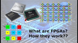
- FPGA
Field-Programmable Gate Array, a type of digital circuit that can be configured by the user after manufacturing.
- HDL
Hardware Description Language; languages used to describe the structure and behavior of electronic systems.
- Synthesis
The process of compiling HDL code into a gate-level netlist.
- Netlist
A description of the electronic circuit in terms of its components and their interconnections.
- Simulation
The process of using software to verify that a design behaves as intended before hardware implementation.
- Bitstream
The binary file used to configure an FPGA with a specific design.
- Testing and Debugging
The process of validating the design and fixing any issues in the final production.
Reference links
Supplementary resources to enhance your learning experience.