
Finite State Machine with Datapath (FSMD) Model: The Blueprint
Interactive Audio Lesson
Listen to a student-teacher conversation explaining the topic in a relatable way.
Introduction to FSMD
🔒 Unlock Audio Lesson
Sign up and enroll to listen to this audio lesson

Today, we're diving into the FSMD model, which stands for Finite State Machine with Datapath. Can anyone tell me why this model is essential for designing single-purpose processors?

Is it because it separates control logic from data processing?
Exactly! The FSM acts as the controller, dictating the flow of operations, while the datapath carries out the data processing tasks. By clearly separating these functions, we minimize errors and enhance efficiency. Remember: the controller dictates 'what' to do and 'when', while the datapath handles 'how' it's done.

So, how does the FSM work in practice?
Great question! The FSM transitions between states based on input conditions or signal statuses from the datapath. For example, if a calculation is complete, the FSM will move to the next state based on that signal.

What kind of operations can happen in the datapath?
The datapath typically includes registers for storage, functional units for arithmetic functions, and multiplexers for directing data. Together, they realize the computational requirements defined by the FSM.
To summarize, the FSMD model's division facilitates error reduction and efficiency by distinctly managing control and data operations. Any questions?
Translating Algorithms into FSMD
🔒 Unlock Audio Lesson
Sign up and enroll to listen to this audio lesson

Next, let's discuss how we can translate high-level algorithms into an FSMD representation. What do you think the first step is in this translation?
I think we need to define the problem clearly first.
Correct! A clear problem definition allows for accurate inputs, outputs, and performance constraints. Can anyone recall how we represent the algorithm for hardware implementation?

We use pseudocode or flowcharts to outline the steps.
Precisely! Using these representations, we can then identify how the operations will map to registers and functional units on the datapath. For example, variables from the algorithm must be linked to specific registers.
So, each operation in the algorithm corresponds to an action in the FSMD?
Yes, each assignment or operation dictates how we route data and control signals in the datapath. It's all about ensuring that the flow aligns correctly with the controls issued by the FSM.
In summary, the translation process from algorithms to FSMD involves defining the problem, expressing it in high-level terms, and mapping each component to the FSMD. Let’s recap: identifying variables, determining operations, and ensuring flow mapping is key!
FIR Filter Example
🔒 Unlock Audio Lesson
Sign up and enroll to listen to this audio lesson
Now, let's apply what we've learned to a practical example: a Finite Impulse Response (FIR) filter. Can someone explain the FIR filter’s core function?
It processes an input signal to produce a filtered output based on coefficient multiplications.
Exactly! In our FSMD for the FIR filter, we define states for loading inputs, processing data through multipliers, and storing results. What components do you think we’ll need in the datapath?
We'll definitely need registers for the input and multiplier results, plus adders to combine those results.
Correct! Your understanding of component placement in the datapath is crucial for the FIR filter's operation. It will consist of registers, multipliers, and adders, all interlinked to perform the filtering operations efficiently.
How do the FSM states look for the FIR filter?
In a simplified FSMD for the FIR filter, we could have states like 'IDLE', 'LOAD_INPUTS', 'MULTIPLY', and 'ADD'. Each state corresponds to a specific task in the computation flow.
To wrap, our FIR filter example illustrates how the FSMD model is employed in real scenarios, showing clearly defined states and necessary datapath components. Any final questions?
Key Concepts of FSMD
🔒 Unlock Audio Lesson
Sign up and enroll to listen to this audio lesson
Before we conclude, let's review some key concepts of the FSMD model. What do you think is the primary role of the FSM?
The FSM controls the sequence of operations in the datapath.
Right! Now, what past concepts should remind us about how registers function within the datapath?
Registers hold variables and are loaded based on control signals from the FSM.
Exactly! Control signals govern when to read or write data in those registers. Can anyone connect the dots on what happens when we define operations like multiplication in the FSM?
The FSM will trigger the multiplier to perform the operation when the correct state is reached!
Well done! Summing up, the FSM orchestrates control, while registers and functional units within the datapath carry out the specifics. This synergy allows for efficient SPP design.
Introduction & Overview
Read summaries of the section's main ideas at different levels of detail.
Quick Overview
Standard
The FSMD model serves as a critical blueprint for designing single-purpose processors by integrating control logic and data manipulation components. This section outlines the basics of the FSMD model, detailing how algorithms can be translated into a structured FSMD representation, essential components of the datapath, and the interconnections between them.
Detailed
Finite State Machine with Datapath (FSMD) Model: The Blueprint
The FSMD is a canonical model used primarily for designing synchronous digital systems, especially single-purpose processors (SPPs). It fundamentally segregates the control and data handling mechanisms into logical units. The control element, represented by a Finite State Machine (FSM), governs the operational sequence, managing transitions between states based on internal signals that reflect computational conditions. The datapath is responsible for storing and manipulating the data, implementing all arithmetic and logical operations. This section discusses how to translate high-level algorithms into actionable FSMD components while shedding light on how persistent variables in algorithms associate with registers and how assignments, operations, and control flows are managed within the model. An illustrative example featuring a Finite Impulse Response (FIR) filter showcases the practical implementation of the FSMD model. A clear understanding of this system allows for the creation and optimization of efficient hardware designs, fulfilling specific computational tasks in embedded systems.
Youtube Videos


Audio Book
Dive deep into the subject with an immersive audiobook experience.
Introduction to FSMD: The Synergy of Control and Data
Chapter 1 of 4
🔒 Unlock Audio Chapter
Sign up and enroll to access the full audio experience
Chapter Content
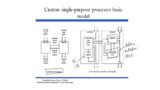
The FSMD is the canonical model for designing synchronous digital systems, especially single-purpose processors. It elegantly separates the control logic (what to do and when) from the data processing logic (how to do it).
- Finite State Machine (FSM) - The Controller: This is the "brain" of the SPP. It dictates the sequence of operations. It transitions between a finite number of states, each representing a distinct phase or step in the algorithm. Transitions are triggered by internal conditions (status signals from the datapath) or external inputs. In each state, the FSM generates control signals that orchestrate the operations within the datapath.
- Datapath - The Data Processor: This is the "muscle" of the SPP. It comprises the hardware units that store and manipulate data. These include:
- Registers: For storing variables and intermediate results.
- Functional Units: Logic blocks that perform arithmetic (adders, multipliers, ALUs) and logical operations (AND, OR, XOR).
- Multiplexers: For selecting data paths.
- Interconnections: Wires that connect these components.
- Interaction: The controller provides control signals to the datapath (e.g., "load register A," "enable adder," "select input 0 on mux"). The datapath, in turn, provides status signals (conditions) back to the controller (e.g., "result is zero," "overflow occurred") that influence the next state transition of the FSM.
Detailed Explanation
In this chunk, we learn about the FSMD model, which combines two main elements: the finite state machine (FSM) and the datapath. The FSM acts as the control center or brain of the single-purpose processor (SPP), directing operations in a designated sequence based on its various states.
The FSM transitions between these states, which represent different steps in processing an algorithm. Each transition can be triggered by certain conditions, including signals from the datapath or external inputs. The FSM generates control signals to manage operations in the datapath effectively.
The datapath itself is the part of the system that handles the actual data operations. It consists of registers, functional units (like adders and multipliers), multiplexers to route data, and the necessary wiring for connections. Overall, the FSMD model separates out the logic for control and the logic for data manipulation, making it easier to design and understand complex digital systems.
Examples & Analogies
Think of the FSMD model like an orchestra. The FSM represents the conductor, who directs the musicians (the datapath) on when to play each note (execute specific operations). Just as the conductor sets the tempo and cues different sections of the orchestra based on the score (the algorithm), the FSM controls the sequence of operations based on the flow of data, ensuring everything works harmoniously.
Translating Algorithmic Constructs into FSMD States and Operations
Chapter 2 of 4
🔒 Unlock Audio Chapter
Sign up and enroll to access the full audio experience
Chapter Content
This is the most critical step in conceptualizing your SPP. You systematically map each part of your algorithm to components and actions within the FSMD.
- Variable Declarations: Each persistent variable in your algorithm (X_prev1, X_prev2 in our FIR example) will typically map to a dedicated register in the datapath. Inputs and outputs will also be associated with registers or I/O ports.
- Assignment Statements (variable = expression): These require routing data. The expression part dictates the functional units needed (e.g., term0 = c0 * current_input_x requires a multiplier). The result of the expression needs to be written into the target variable's register. This means enabling the write operation of that register (a control signal from the FSM) and ensuring the correct data path is selected to its input (using a multiplexer, if multiple sources can write to it).
- Example (FIR): X_prev2 = X_prev1 implies routing the output of X_prev1 register to the input of X_prev2 register, and asserting load_X_prev2 control signal.
Detailed Explanation
This chunk focuses on how to effectively translate algorithmic structures into the FSMD model. The first step involves identifying and mapping each variable in the algorithm to a corresponding register within the datapath. For example, if an algorithm uses variables to store values over time, these variables must have dedicated registers to hold their data.
Next, we look at assignment statements, which involve operations like data routing and processing. When you perform an assignment (like updating a variable with a computed value), it necessitates identifying which functional units are needed (such as multipliers for multiplication) and ensuring that the computed value is written to the proper register. This involves signaling through the FSM to enable the writing process and selecting the correct data path.
The FIR filter example illustrates this, where shifting data between registers is a straightforward operation that must be controlled explicitly through the FSM's signals.
Examples & Analogies
To visualize this, consider a kitchen where different ingredients (variables) are stored in labeled containers (registers). When you’re preparing a recipe (algorithm), you need to know which ingredients to use and how to manipulate them. If one ingredient needs to be measured and then transferred to another container, you not only need to take the ingredient out (assignment), but also ensure you have the right measuring tools (functional units) in place and that the container is ready to receive (data routing). Just as careful planning and execution are crucial in cooking, the same is true for translating algorithms into an FSMD model.
Illustrative Example: FSMD for FIR Filter
Chapter 3 of 4
🔒 Unlock Audio Chapter
Sign up and enroll to access the full audio experience
Chapter Content
Let's refine the FIR example into an FSMD. Assume data is W-bits wide.
- Datapath Components:
- Registers: X_reg (for current_input_x), X_prev1_reg, X_prev2_reg.
- Multipliers: MUL0, MUL1, MUL2 (or a single shared multiplier).
- Adders: ADD0, ADD1 (or a single shared adder).
- Input ports: DATA_IN (for current_input_x), C0_IN, C1_IN, C2_IN.
- Output port: RESULT_OUT.
- Muxes: For routing data to register inputs if they can be loaded from multiple sources.
- FSM States & Transitions:
- IDLE_STATE:
- Actions: Wait for start_signal.
- Transitions: If start_signal is asserted, transition to LOAD_INPUTS_AND_SHIFT.
- LOAD_INPUTS_AND_SHIFT_STATE:
- Actions:
- X_prev2_reg <- X_prev1_reg (Control: load_X_prev2, mux_X_prev2_sel = X_prev1_reg_out).
- X_prev1_reg <- X_reg (Control: load_X_prev1, mux_X_prev1_sel = X_reg_out).
- X_reg <- DATA_IN (Control: load_X_reg, mux_X_reg_sel = DATA_IN).
- Transitions: Unconditionally transition to MULTIPLY_STATE.
Detailed Explanation
In this chunk, we present a refined example of how to apply the FSMD model to create a finite impulse response (FIR) filter. We define the specific components needed in the datapath, including registers for storing input values and intermediate results, as well as functional units like multipliers and adders. These components work together to process data effectively.
The FSM states and transitions describe how the processor reacts to various signals. For instance, the system begins in an IDLE state, waiting for a start signal. Once it receives this signal, it moves to the LOAD_INPUTS_AND_SHIFT state, where it prepares the necessary inputs for processing. Each state dictates specific actions and outlines how the controller and datapath will interact during this process. The transition from one state to another is essential for the flow of operations in the FSMD.
Examples & Analogies
Imagine a delivery system for packages. The IDLE_STATE is like a delivery truck waiting at the warehouse for an order. Once an order is received (start_signal), the truck prepares to load packages (LOAD_INPUTS_AND_SHIFT_STATE) by gathering the necessary items. This process involves moving packages from their storage locations (registers) onto the truck (datapath components) in an organized manner, before hitting the road to deliver (carrying out computations in subsequent FSM states). Just as route planning and execution are crucial for successful deliveries, the same principle applies to managing the flow in an FSMD.
Partitioning FSMD into Controller and Datapath
Chapter 4 of 4
🔒 Unlock Audio Chapter
Sign up and enroll to access the full audio experience
Chapter Content
Once the FSMD is conceptualized, we physically separate it into its two interdependent units.
- Controller Design: The Brain of the SPP
- Role and Function: The controller is a sequential circuit responsible for generating the necessary control signals to orchestrate the datapath's operations in the correct sequence. It interprets inputs (external controls, status signals from datapath) and current state to determine the next state and corresponding outputs.
- Extracting Control Logic: States: Identify all the distinct states identified in your FSMD (e.g., IDLE, LOAD_INPUTS, MULTIPLY, ADD1, ADD2, DONE). Transitions: Define the conditions under which the FSM moves from one state to another (e.g., start_signal, zero_flag). Control Signals: For each state, list all the specific control signals that must be asserted (set to '1') or de-asserted (set to '0') to make the datapath perform its intended operation in that cycle. These are the outputs of the controller.
- Datapath Design: The Muscles of the SPP
- Role and Function: The datapath is the collection of hardware units that store, manipulate, and transfer data as instructed by the controller. It performs the actual computations.
Detailed Explanation
In this closing chunk, we focus on how to physically separate the FSMD into two distinct components: the controller and the datapath. The controller, referred to as the 'brain' of the processor, is tasked with directing operations by generating control signals based on its current state and input conditions. This involves determining what to do next and ensuring that the right actions are taken in the datapath.
On the other hand, the datapath consists of all the hardware components that enact the actual data manipulation processes, such as arithmetic calculations and data storage. This separation allows for a clearer understanding of how control signals are derived and utilized to manage the various operations that take place within the processor, ensuring that both components work together efficiently.
Examples & Analogies
Let's liken the controller and datapath to a movie director and the actors on set. The director (controller) orchestrates when each scene is shot, guides the actors (datapath) on what to do, and makes decisions based on the flow of the film (current states and conditions). The actors perform their roles, manipulating the script (data processing) under the direction provided. This collaboration is vital for producing a cohesive movie (successful algorithm execution), highlighting how each part plays a crucial role in the overall system.
Key Concepts
-
FSMD Model: A structured way to model single-purpose processors by separating control from data handling.
-
FSM: The Finite State Machine acting as the controller of the FSMD.
-
Datapath: The part of the architecture where data storage and processing occur.
-
Control Signals: Signals produced by the FSM to direct operations in the datapath.
-
Registers: Essential components for temporarily holding data and variables.
Examples & Applications
An FIR filter uses the FSMD model to regulate the calculation of filtered outputs based on input coefficients.
In a GCD processor, states in the FSM direct the flow of mathematical operations to compute the greatest common divisor efficiently.
Memory Aids
Interactive tools to help you remember key concepts
Rhymes
FSM and Datapath, a duo in sync,
Stories
Imagine a factory where the FSM is the manager deciding what parts get used when, while the datapath is the assembly line putting things together in precise order.
Memory Tools
C-D-R-F: Control Drives the Registers and Functions, remembering the roles of the FSM and datapath.
Acronyms
FSD
Finite State Determines operations.
Flash Cards
Glossary
- FSMD
Finite State Machine with Datapath, a model for designing digital systems that separates control logic from data processing logic.
- Control Logic
Logic that dictates the sequence and conditions of operations within a digital system.
- Data Processing Logic
The hardware components responsible for executing operations on data.
- Registers
Storage elements that hold data temporarily for processing within the datapath.
- Multiplexer
A device that selects one of many inputs and forwards the selected input to a single output line.
- Functional Units
Hardware blocks that perform specific operations (arithmetic or logic) in the datapath.
- State Transition
The process of changing from one state to another in a finite state machine based on inputs or conditions.
Reference links
Supplementary resources to enhance your learning experience.