
Module 2.2: Designing Custom Single-Purpose Processors - The FSMD Approach
Interactive Audio Lesson
Listen to a student-teacher conversation explaining the topic in a relatable way.
Problem Description and Algorithmic Representation
🔒 Unlock Audio Lesson
Sign up and enroll to listen to this audio lesson

To start designing a Single-Purpose Processor, we need a clear problem definition. What are some important aspects we should include?

We need to identify inputs and outputs!
Exactly! Inputs tell us what data we'll work with, while outputs define what we want to achieve. What else?

We should also specify performance constraints, like speed and power?
Right again! In addition to performance constraints, we must define any resource constraints. Let’s think about how we can represent our algorithms. What notations come to mind?

Pseudocode is a good one because it's easy to understand.

I think flowcharts might work well too!
Great suggestions! Using pseudocode and flowcharts helps clarify our algorithm’s logic without diving into hardware details. Let's move on to a practical example, like the FIR filter. How would we express this algorithmically?
We could represent it with the formula: y[n] = c0 * x[n] + c1 * x[n-1] + c2 * x[n-2].
Good! Creating clear representations makes it easier for us to build the actual processor. Always remember the importance of planning. Let’s summarize today’s lesson.
We discussed the importance of defining inputs, outputs, and constraints. We also touched upon using pseudocode and flowcharts in this early stage. Remember, clarity and precision are essential for efficient design!
Finite State Machine with Datapath (FSMD) Model
🔒 Unlock Audio Lesson
Sign up and enroll to listen to this audio lesson

Now, let's delve into the FSMD model. Can anyone explain how it functions?
The FSM controls the process by transitioning between states based on input conditions.
Correct! What kind of components do we find in the datapath?
Registers and functional units, right? They perform the computations.
Absolutely! The interaction between the controller and the datapath is crucial. Can someone elaborate on how they interact?
The controller sends control signals to the datapath, directing it on what operations to perform.
Perfect! Each state in the FSM corresponds to an operation in the datapath, forming a harmonious system. As we move forward, keep in mind how these elements interact to achieve our design goals. Any final thoughts on FSMD?
I think understanding both the FSM and the datapath components is key to successful design.
Exactly, great summary! It’s all about how these components work together. Let’s move on to translating algorithmic constructs next for practical applications.
Translating Algorithmic Constructs into FSMD
🔒 Unlock Audio Lesson
Sign up and enroll to listen to this audio lesson
Next, let’s discuss how to map our algorithm to the FSMD. What are some constructs we should consider?
We should look at variables, assignments, and operations like additions or logical comparisons.
Good points! Now, what would we do with a variable declared in our algorithm?
We need to allocate registers in the datapath for those variables.
Exactly! Each variable must have a dedicated storage. Let's connect this back to our FIR example. If we have assignments, how would that translate?
We would need to enable write operations to the appropriate registers and route the data correctly.
Correct! Remember, the goal is to ensure that each operation is efficiently executed by the correct hardware components. Let’s review key methods for controls.
So, we can use state transitions to capture if statements?
Exactly! This interaction outlines your control flow. Keep this structure in mind for our future discussions. Let’s summarize today’s insights!
Today, we discussed how to map variables and operations directly to hardware implementations in the FSMD. Capturing control flow via states is key for system efficiency.
Partitioning FSMD into Controller and Datapath
🔒 Unlock Audio Lesson
Sign up and enroll to listen to this audio lesson
Let’s conclude our lesson by discussing partitioning FSMD into its main components. Who can define the role of the controller?
The controller generates control signals based on state transitions.
Correct! Now what about the datapath?
It’s the part where the actual computation takes place, like storing and manipulating data.
Great! Understanding this division is crucial. Why is it necessary to keep these parts distinct?
It allows us to optimize each component individually while ensuring they work together effectively.
Well said! Optimizing each section enhances performance while maintaining functionality. Remember this as we proceed to implementation. Let’s recap our discussion.
We defined the roles of the controller and datapath, emphasizing their distinct functions in SPP design. Maintaining this separation aids in efficient and optimized hardware development.
Introduction & Overview
Read summaries of the section's main ideas at different levels of detail.
Quick Overview
Standard
In this section, we explore how to effectively convert high-level problem specifications into structured FSMD representations, detailing the interaction between control logic and data processing for efficient hardware implementation of Single-Purpose Processors. Understanding these concepts is crucial for achieving optimized and efficient embedded systems.
Detailed
Module 2.2: Designing Custom Single-Purpose Processors - The FSMD Approach
This section is critical in the design of Single-Purpose Processors (SPPs) as it guides how to convert high-level algorithms into structured Finite State Machine with Datapath (FSMD) representations. The FSMD model delineates the control logic and data processing flow, ensuring clarity and efficiency in hardware design.
Key Points:
- Problem Description and Algorithmic Representation: Clear definitions of inputs, outputs, transformations, and constraints are vital. The high-level algorithm represents the solution without delving into hardware specifics.
- Common notations include pseudocode, C/C++ code, and flowcharts.
- Example: A simple Finite Impulse Response (FIR) filter algorithm demonstrates how to express computation clearly.
- Finite State Machine with Datapath (FSMD) Model: The FSMD separates control logic from data handling, creating a balanced system architecture.
- FSM as the Controller: It transitions based on conditions and outputs control signals to the datapath.
- Datapath as the Data Processor: Comprising registers, functional units, and multiplexers, it executes the computations dictated by the FSM.
- Translating Algorithmic Constructs into FSMD States and Operations: Each algorithm component corresponds with hardware elements in the FSMD.
- This includes mapping variables to registers, operations to functional units, and conditions to controllers.
- An illustrative example focuses on the FIR filter, showing how various computational steps translate into an FSMD framework.
- Partitioning FSMD into Controller and Datapath: The final step involves distinct design processes for the controller (generates control signals) and datapath (stores and processes data) to achieve a functional SPP. Together, these components yield a robust design ready for implementation.
Understanding how to effectively design and implement the FSMD model is essential for students of embedded systems, as it lays the foundation for developing efficient and specialized hardware accelerators.
Youtube Videos


Audio Book
Dive deep into the subject with an immersive audiobook experience.
Problem Description and Algorithmic Representation: The Starting Point
Chapter 1 of 3
🔒 Unlock Audio Chapter
Sign up and enroll to access the full audio experience
Chapter Content
Problem Description and Algorithmic Representation: The Starting Point
- Defining the Problem: Before any design work begins, a clear, unambiguous, and complete specification of the problem is essential. What are the inputs? What are the outputs? What is the exact transformation or computation required? What are the performance constraints (speed, throughput, latency)? What are the resource constraints (area, power)?
- High-Level Algorithmic Representation: Once the problem is defined, the first step towards hardware design is to express the solution as a high-level algorithm. This step is crucial because it allows us to reason about the logic and control flow without immediately worrying about hardware details.
- Common Notations:
- Pseudocode: An informal, high-level description of an algorithm's operating principle. It uses the structural conventions of programming languages but is intended for human reading rather than machine execution.
- C/C++ Code: A common starting point for hardware design, as many algorithms are initially developed and verified in these languages. Tools exist to synthesize hardware from a subset of C/C++ (High-Level Synthesis - HLS).
- Flowcharts: Graphical representation of an algorithm, showing steps as boxes of various kinds and their order by connecting them with arrows. Useful for visualizing control flow.
- Importance: This step helps in:
- Clarity: Ensuring a shared understanding of the problem and its solution among designers.
- Verification: The algorithm can be simulated and tested in software to ensure its correctness before committing to costly hardware design.
- Abstraction: It allows focusing on the 'what' (the logic) before the 'how' (the hardware implementation).
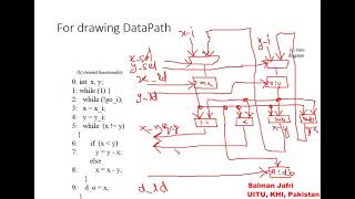
- Example: A Simple Finite Impulse Response (FIR) Filter: Let's consider a simple 3-tap FIR filter, commonly used in DSP. y[n] = c0 * x[n] + c1 * x[n-1] + c2 * x[n-2] Where:
- y[n] is the current output sample.
- x[n] is the current input sample.
- x[n-1] and x[n-2] are previous input samples (delayed versions).
- c0, c1, c2 are filter coefficients (constants). Pseudocode representation for a single output calculation:
    function Compute_FIR_Output(current_input_x, coeff_c0, coeff_c1, coeff_c2):
      // Assume registers for previous inputs: X_prev1, X_prev2
      // Shift operations (oldest input drops, current input becomes latest previous)
      X_prev2 = X_prev1
      X_prev1 = current_input_x
      // Perform multiplications
      term0 = coeff_c0 * current_input_x
      term1 = coeff_c1 * X_prev1
      term2 = coeff_c2 * X_prev2
      // Perform additions
      sum01 = term0 + term1
      final_output = sum01 + term2
      return final_output
Detailed Explanation
In this chunk, we start with a crucial step in designing custom single-purpose processors: defining the problem and representing the algorithm. First, before any design takes place, it's paramount to establish a clear understanding of the problem. This involves identifying the inputs, outputs, and the transformation required, along with any performance constraints like speed and power.
Once the problem is known, the next step is to express the solution algorithm at a high level. This high-level algorithm can be expressed in various notations:
- Pseudocode: A human-readable version that describes the steps without worrying about syntax.
- C/C++ Code: Many algorithms start here, as hardware can sometimes be synthesized from this code.
- Flowcharts: Visual representations clarify how the algorithm flows.
The examples, especially the FIR filter, illustrate how to implement computations through clearly defined steps, substituting complex operations for simpler pseudocode, making it easier to transition to hardware design.
Examples & Analogies
Think of designing a meal. Before cooking, you must first understand the recipe, including what ingredients you need (inputs), what the meal should look like (outputs), and any dietary restrictions or cooking time (performance constraints). Once you know what you want to cook, you write down the steps (algorithm) using easy-to-understand instructions, maybe even in a simple drawing if it's a complex dish, to visualize the process. This preparation is essential for a successful cooking experience, just as defining a problem and writing algorithms are vital for designing processors.
Finite State Machine with Datapath (FSMD) Model: The Blueprint
Chapter 2 of 3
🔒 Unlock Audio Chapter
Sign up and enroll to access the full audio experience
Chapter Content
Finite State Machine with Datapath (FSMD) Model: The Blueprint
- Introduction to FSMD: The Synergy of Control and Data
- Finite State Machine (FSM) - The Controller: This is the "brain" of the SPP. It dictates the sequence of operations. It transitions between a finite number of states, each representing a distinct phase or step in the algorithm. Transitions are triggered by internal conditions (status signals from the datapath) or external inputs. In each state, the FSM generates control signals that orchestrate the operations within the datapath.
- Datapath - The Data Processor: This is the "muscle" of the SPP. It comprises the hardware units that store and manipulate data. These include:
- Registers: For storing variables and intermediate results.
- Functional Units: Logic blocks that perform arithmetic (adders, multipliers, ALUs) and logical operations (AND, OR, XOR).
- Multiplexers: For selecting data paths.
- Interconnections: Wires that connect these components.
- Interaction: The controller provides control signals to the datapath (e.g., "load register A," "enable adder," "select input 0 on mux"). The datapath, in turn, provides status signals (conditions) back to the controller (e.g., "result is zero," "overflow occurred") that influence the next state transition of the FSM.
- Translating Algorithmic Constructs into FSMD States and Operations: This is the most critical step in conceptualizing your SPP. You systematically map each part of your algorithm to components and actions within the FSMD.
- Variable Declarations: Each persistent variable in your algorithm (X_prev1, X_prev2 in our FIR example) will typically map to a dedicated register in the datapath. Inputs and outputs will also be associated with registers or I/O ports.
- Assignment Statements (variable = expression): These require routing data. The expression part dictates the functional units needed (e.g., term0 = c0 * current_input_x requires a multiplier). The result of the expression needs to be written into the target variable's register. This means enabling the write operation of that register (a control signal from the FSM) and ensuring the correct data path is selected to its input (using a multiplexer, if multiple sources can write to it).
- Example (FIR): X_prev2 = X_prev1 implies routing the output of the X_prev1 register to the input of the X_prev2 register, and asserting the load_X_prev2 control signal.
Detailed Explanation
This chunk dives into the Finite State Machine with Datapath (FSMD) model, instrumental in designing custom processors. The FSMD represents the synergy of control and data within a system.
- Finite State Machine (FSM): This acts as the controller of the SPP, managing the sequence of operations by transitioning through several states, each signifying different steps in the algorithm's execution. It generates control signals orchestrating the datapath's action based on conditions.
- Datapath: This is the data processing side of the model, containing components like registers and functional units that handle data storage and processing tasks. The interaction between controller and datapath is vital for the execution of operations, as the controller sends commands while receiving feedback on the current state of operations.
- Translating Algorithm to FSMD: This involves mapping each variable and computational expression from the original algorithm to the corresponding components in the FSMD design. Each variable would locate to a specific register, and operations translate directly into functional units within the datapath, enabling the processor to operate effectively.
Examples & Analogies
Imagine a traffic light system in a city that switches colors based on time or traffic conditions (the FSM). It controls when cars can go or stop (the datapath). Each light's state (red, yellow, green) represents a phase in managing traffic. The system dictates when each light should change and receives signals from sensors (like cars waiting) to decide the next action. Similarly, the FSMD model determines the operations of a processor, managing the sequence and execution of mathematical tasks.
Partitioning FSMD into Controller and Datapath: The Two Pillars
Chapter 3 of 3
🔒 Unlock Audio Chapter
Sign up and enroll to access the full audio experience
Chapter Content
Partitioning FSMD into Controller and Datapath: The Two Pillars
- Controller Design: The Brain of the SPP
- Role and Function: The controller is a sequential circuit responsible for generating the necessary control signals to orchestrate the datapath's operations in the correct sequence. It interprets inputs (external controls, status signals from datapath) and current state to determine the next state and corresponding outputs.
- Extracting Control Logic:
- States: Identify all the distinct states identified in your FSMD (e.g., IDLE, LOAD_INPUTS, MULTIPLY, ADD1, ADD2, DONE).
- Transitions: Define the conditions under which the FSM moves from one state to another (e.g., start_signal, zero_flag).
- Control Signals: For each state, list all the specific control signals that must be asserted (set to '1') or de-asserted (set to '0') to make the datapath perform its intended operation in that cycle. These are the outputs of the controller.
- Status Signals: Identify all inputs the controller needs from the datapath or external world to make decisions about state transitions. These are the inputs to the controller.
- Representing the Controller as a Pure Finite State Machine (FSM):
- State Diagram: A graphical representation showing states as nodes and transitions as directed edges, labeled with input conditions and output control signals.
- State Table: A tabular representation listing current state, inputs, next state, and outputs for all possible combinations.
- Implementing the FSM:
- State Register: A bank of D-type flip-flops (typically) whose outputs represent the current state. The number of flip-flops depends on the number of states (e.g., for 5 states, 3 flip-flops: lceillog_25rceil=3).
- Next-State Logic (Combinational Logic): This is a combinational circuit that takes the current state (from the state register) and the controller inputs (status signals, external controls) and calculates the next state to be loaded into the state register at the next clock edge. This logic is derived from the state table.
- Output Logic (Combinational Logic): This is another combinational circuit that takes the current state (and sometimes, the controller inputs, for Mealy-type FSMs) and generates all the necessary control signals that drive the datapath. This logic is also derived from the state table.
Detailed Explanation
In this chunk, we explore how to partition the FSMD into its two essential components: the controller and the datapath. The controller is like the brain of the processor, responsible for managing and directing the execution of operations in the datapath.
- Role and Function: The controller controls the sequence of operations needed to execute a task, generating control signals and interpreting inputs to determine state transitions.
- Control Logic Components:
- States are unique phases that the FSM can be in. Example states might include IDLE, LOAD_INPUTS, MULTIPLY, etc.
- Transitions determine how the FSM moves from one state to another based on inputs.
- Control Signals are commands generated by the controller for the datapath to follow.
- Representing the Controller: The controller can be illustrated using state diagrams or tables that show how it behaves under various input conditions.
- Implementing the FSM: This involves creating circuits using D-type flip-flops to represent states, logic circuits for determining the next state and generating output control signals.
By breaking down the design in this manner, we ensure clarity in how both components work together to facilitate SPP functionality.
Examples & Analogies
Think of a conductor directing an orchestra. The conductor (controller) signals different sections of musicians (datapath) to play at specific times, determining the flow and timing of the entire performance. The conductor reads the sheet music (the algorithm) and communicates cues through gestures (control signals) to ensure everything harmonizes perfectly. Similarly, the controller orchestrates the operations within the processor design, ensuring each part functions correctly at the right moment.
Key Concepts
-
Finite State Machine (FSM): A method for designing control logic based on states and transitions.
-
Datapath: The section of the SPP where actual data processing occurs.
-
Control Signals: Directions sent from the FSM to the datapath specifying actions to take.
-
Registers: Storage elements in the datapath that hold data during processing.
Examples & Applications
A Finite Impulse Response (FIR) filter algorithm for digital signal processing.
Pseudocode examples representing computational steps for designing SPPs.
Memory Aids
Interactive tools to help you remember key concepts
Rhymes
FSM and datapath, they work as a team, control and logic, executing our dream.
Stories
Once upon a time, in a land of circuits, there was a magical FSM that guided the datapath to perform fantastic computations. Together, they solved problems and built processors, creating wonders in the kingdom of embedded systems.
Memory Tools
FSMD = F: Finite State, S: Sequence, M: Machine, D: Datapath. Remember these letters to outline how control meets data!
Acronyms
DPS = Datapath, Processing, Signals. This helps recall what the datapath does
processing data with control signals.
Flash Cards
Glossary
- Finite State Machine (FSM)
A computation model represented by states and transitions that controls the sequence of operations within a system.
- Datapath
The portion of a processor where arithmetic and logical operations are performed and data is stored.
- Control Signals
Signals generated by the controller to direct operations in the datapath.
- Registers
Storage locations within the datapath used to hold intermediate results during computations.
- Pseudocode
A high-level representation of an algorithm using informal language that resembles programming syntax.
- Flowchart
A visual representation of an algorithm that uses shapes and arrows to denote processes and their order.
Reference links
Supplementary resources to enhance your learning experience.