
Partitioning FSMD into Controller and Datapath: The Two Pillars
Interactive Audio Lesson
Listen to a student-teacher conversation explaining the topic in a relatable way.
Introduction to FSMD and Its Components
🔒 Unlock Audio Lesson
Sign up and enroll to listen to this audio lesson

Today we will explore the FSMD, which stands for Finite State Machine with Datapath. It is critical to understand how this model is structured, especially the separation of the controller and the datapath.

Can you explain what the FSMD actually does?
Of course! The FSMD serves as a blueprint for designing hardware by embodying both the control flow of operations and the necessary data processing mechanisms. We will learn how it separates control logic from data manipulations, optimizing our design for performance.

What are ‘controller’ and ‘datapath’ specifically?
Great question! The controller orchestrates the sequence of operations, while the datapath carries out the actual calculations and data handling. Remember that thinking of them as 'the brain' and 'the muscles' can help you recall their roles.

So the controller is like a conductor of an orchestra?
Exactly, and the datapath is the orchestra itself, executing the performance together. Both are essential for the final product!
To summarize, the FSMD is comprised of a controller that manages sequence and logic operations, while the datapath processes data through various hardware units. This separation is crucial for efficient SPP design.
Detailed Functions of the Controller
🔒 Unlock Audio Lesson
Sign up and enroll to listen to this audio lesson

Let us dive deeper into the controller. It operates as an FSM and is responsible for generating control signals needed by the datapath.
What kind of control signals are we talking about?
Control signals can include commands like 'load data into register' or 'execute multiplication'. These signals guide the datapath through its operations based on current states and inputs.

How does the controller know when to change states?
The controller uses conditions from the datapath, represented in status signals, as triggers for state transitions. This requires clear identification of all states and the corresponding transition conditions.
Can you give an example of a state in the controller's sequence?
Sure! Think of an 'IDLE' state, which is where the FSM starts, waiting for a start signal. Once received, it transitions to the next operational state.
In conclusion, the controller's role is crucial as it manages control signals and state transitions, directly impacting how smoothly the datapath operates.
Overview of the Datapath
🔒 Unlock Audio Lesson
Sign up and enroll to listen to this audio lesson
Moving on, let’s discuss the datapath. This is where the actual data processing occurs in the SPP.
What components make up a datapath?
The datapath includes registers for storage, functional units such as adders and multipliers for arithmetic operations, and interconnections like multiplexers to route data.
How do those components work together?
Excellent question! The controller sends control signals that tell the datapath what operations to perform and when to load or unload data from the registers.
What role do registers play specifically?
Registers hold variables or intermediate results across multiple cycles. They are vital in ensuring that we keep track of necessary data during computations.
To sum up, the datapath is composed of essential components like registers and functional units that work under the direction of the controller to execute computations effectively.
Interconnection Between Controller and Datapath
🔒 Unlock Audio Lesson
Sign up and enroll to listen to this audio lesson
Now, let’s discuss how the controller and datapath interface with each other.
So, how do they communicate?
Good question! The controller sends out control signals to execute certain operations on the datapath, while the datapath sends back status signals to inform the controller of its current state.
What happens if the controller doesn’t get the right status signal?
If the signals are incorrect, it can lead to erroneous operations, making it crucial for these to be properly defined and managed. This intercommunication is fundamental for synchronization.
Can you explain any scenarios where improper communication might break the system?
Definitely! For example, if a signal indicates the data is ready when it’s not, the controller might proceed to the next state prematurely, causing the entire sequence to fail.
In conclusion, the interconnection between the controller and datapath is a vital aspect of SPP design, impacting how efficiently operations are executed based on the signals exchanged.
Final Thoughts and Improvements
🔒 Unlock Audio Lesson
Sign up and enroll to listen to this audio lesson
As we wrap up this section, let's look at how we could improve the efficiency of our controller and datapath.
What improvements can be made?
By optimizing control signal timing and ensuring that the datapath operations are pipelined, we can significantly enhance throughput.
What about reducing complexity?
That's a key area! Simplifying control logic while maintaining clarity can reduce errors and improve performance. Modular designs also make it easier to test and refine individual units.
Are there any tools that can help with this?
Yes, Electronic Design Automation (EDA) tools are excellent for optimizing SPP designs. They can suggest refinements based on simulated behavior.
To summarize, continual improvements and optimizations of the controller and datapath interactions can lead to significant performance gains in custom processor designs.
Introduction & Overview
Read summaries of the section's main ideas at different levels of detail.
Quick Overview
Standard
In this section, we explore how the FSMD is divided into its two pivotal components, the controller and the datapath. The controller manages the sequencing and decision-making processes, while the datapath performs the actual data operations and manipulations. Understanding this partitioning is crucial for implementing an efficient single-purpose processor (SPP).
Detailed
Partitioning FSMD into Controller and Datapath: The Two Pillars
Introduction
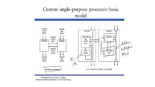
In the design of Single-Purpose Processors (SPPs), the Finite State Machine with Datapath (FSMD) is openly analyzed and separated into two key components: the controller and the datapath. This partitioning is not only essential for understanding the structure of the SPP but also improves the modularity and efficiency of the design.
The Controller: The Brain of the SPP
The controller is responsible for generating control signals that dictate how the datapath operates. It interprets inputs (external controls and status signals) and current states to determine subsequent actions. The controller can be thought of as a finite state machine (FSM) that transitions through a series of states, each reflecting a unique phase of operation in the SPP.
Key Functions of the Controller:
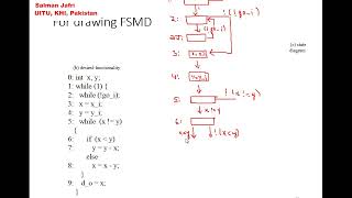
- State Management: Identify distinct states from the FSMD, such as IDLE, LOAD_INPUTS, MULTIPLY, etc.
- Control Logic Extraction: Identify conditions for state transitions and the control signals needed for each state.
- Representation: The controller may be represented graphically (as a state diagram) or in tabular form (state table).
- Implementation: It is realized through state registers and combinational logic that derives next states and control signal outputs.
The Datapath: The Muscles of the SPP
The datapath comprises all hardware components responsible for actual computations, including arithmetic operations, data storage, and manipulations.
Key Functions of the Datapath:
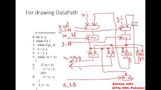
- Registers: Data storage elements that retain values across multiple clock cycles. Each variable in the algorithm corresponds to a dedicated register.
- Functional Units: Include ALUs, dedicated adders, and multipliers that perform necessary computations.
- Interconnects: Wires and multiplexers that route data among the registers and functional units.
- Control Inputs and Outputs: Each component within the datapath receives control signals from the controller and may output status signals (e.g., outputs of comparators) back to the controller.
Conclusion
Understanding the clear distinction between the controller and datapath in the FSMD framework not only enhances the design efficiency of SPPs but also allows for modular and adaptable systems that can be optimized for performance.
Youtube Videos


Audio Book
Dive deep into the subject with an immersive audiobook experience.
Controller Design: The Brain of the SPP
Chapter 1 of 3
🔒 Unlock Audio Chapter
Sign up and enroll to access the full audio experience
Chapter Content
Controller Design: The Brain of the SPP
Role and Function:
The controller is a sequential circuit responsible for generating the necessary control signals to orchestrate the datapath's operations in the correct sequence. It interprets inputs (external controls, status signals from datapath) and current state to determine the next state and corresponding outputs.
Extracting Control Logic:
- States: Identify all the distinct states identified in your FSMD (e.g., IDLE, LOAD_INPUTS, MULTIPLY, ADD1, ADD2, DONE).
- Transitions: Define the conditions under which the FSM moves from one state to another (e.g., start_signal, zero_flag).
- Control Signals: For each state, list all the specific control signals that must be asserted (set to '1') or de-asserted (set to '0') to make the datapath perform its intended operation in that cycle. These are the outputs of the controller.
- Status Signals: Identify all inputs the controller needs from the datapath or external world to make decisions about state transitions. These are the inputs to the controller.
Detailed Explanation
The controller is essentially the decision-making part of the single-purpose processor (SPP). It controls the sequence of operations that the datapath will execute. First, it determines the current state of the processor, which can be understood as where the processor is in the overall computation process (like being in a queue at a coffee shop). Based on input signals and the current state, it decides the next state and sends out control signals to the datapath.
To do this effectively, the controller needs to map out all possible states and transitions. For example, if it's in an IDLE state and the start signal is received (like getting to the front of the line), it will transition to the next operational state (LOAD_INPUTS). Additionally, it will send control signals ensuring the datapath executes the correct actions according to the desired state. Each state can have different control signals associated with it, telling the datapath what to do, such as which computations to execute or which registers to load with new data. This process allows for efficient sequencing of operations in a systematic manner.
Examples & Analogies
Think of the controller as a traffic light system. At any intersection, the light can be green, yellow, or red (these are its states). Based on the current state and inputs (like whether cars are waiting or pedestrians are present), the controller decides to change the light to the next state and sends signals to vehicles and pedestrians about when to stop or go. Just like drivers and pedestrians rely on the lights to know when to act, the datapath relies on control signals from the controller to know which operations to perform.
Datapath Design: The Muscles of the SPP
Chapter 2 of 3
🔒 Unlock Audio Chapter
Sign up and enroll to access the full audio experience
Chapter Content
Datapath Design: The Muscles of the SPP
Role and Function:
The datapath is the collection of hardware units that store, manipulate, and transfer data as instructed by the controller. It performs the actual computations.
Identifying Data Storage Elements (Registers):
- Each variable in your algorithm that needs to hold a value over multiple clock cycles (e.g., X_reg, X_prev1_reg, X_prev2_reg in FIR) will be implemented as a register. A register is essentially a collection of D-flip-flops, all clocked together.
- Registers typically have a load enable input (controlled by the FSM) that dictates when new data is written into them.
- Input/Output ports are often implemented as registers (input registers, output registers) for synchronization and buffering.
Detailed Explanation
The datapath is crucial for executing the instructions that the controller breaks down into actionable tasks. It consists of various components that handle data processing, including registers and functional units (like adders and multipliers). Registers are like storage boxes that keep data safe until it’s needed. Each piece of data (variables) that has to be remembered for future computations is assigned a register.
When the controller tells the datapath what to do, these registers play a key role by holding temporary results and inputs/outputs. For instance, if we have variables representing previous inputs in a calculation (like a filter operation), registers will retain the values of those inputs across multiple cycles so that they can be used later in calculations without losing information, ensuring the correct results are generated at each step.
Examples & Analogies
Imagine the datapath as a workshop where tasks are carried out. The registers are like storage bins where workers place tools and materials they need for their jobs. Workers (those are the functional units) can grab tools from the bins (registers) whenever they need them to complete their tasks. When a foreman (the controller) gives instructions on what jobs to do, the workers know exactly where to find their tools and how to use them to complete the task efficiently.
Controller as a FSM: Representing Logic
Chapter 3 of 3
🔒 Unlock Audio Chapter
Sign up and enroll to access the full audio experience
Chapter Content
Representing the Controller as a Pure Finite State Machine (FSM):
- State Diagram: A graphical representation showing states as nodes and transitions as directed edges, labeled with input conditions and output control signals.
- State Table: A tabular representation listing current state, inputs, next state, and outputs for all possible combinations.
Detailed Explanation
To design an effective controller for an SPP, it is beneficial to represent its operations as a Finite State Machine (FSM). An FSM is structured as a series of states (like different stages in a process) that the controller can be in at any time. A state diagram visually depicts these states as points and the transitions (how it moves from one state to another) as arrows connecting them, along with the conditions under which the transitions occur.
The state table serves as a comprehensive reference, detailing what the controller does in each state, what inputs it requires at that state, and what outputs it generates (like control signals). By organizing and visualizing these elements, designers can ensure clarity and correctness in how the controller will function during operation, paving the way for efficient hardware implementation.
Examples & Analogies
Think of the FSM of a controller like a train schedule. Each train station represents a state where the train can stop. The trains (controller) can move from one station to another based on certain conditions (like 'all passengers have boarded'). The station board (state diagram) shows at which stations the train stops and how it can move between them (transitions). The complete schedule (state table) details what happens at each stop, including timings and operations (such as loading or unloading passengers) to ensure the train runs on time and efficiently.
Key Concepts
-
FSMD: A model that integrates control and data paths.
-
Controller: Directs how operations are sequenced and executed.
-
Datapath: Executes arithmetic operations and data movements.
-
State Transitions: Conditions affecting how the controller changes states.
Examples & Applications
The controller transitions from an IDLE state to LOAD_INPUTS when a start signal is received.
The datapath performs multiplication when instructed by a control signal from the controller.
Memory Aids
Interactive tools to help you remember key concepts
Rhymes
The controller's like a brain, guiding paths without pain.
Stories
Imagine a conductor leading an orchestra where each musician represents a different component of the datapath. Together, they create a beautiful symphony, just as the controller and datapath work seamlessly to form an efficient processor.
Memory Tools
C-D-P: Controller directs, Datapath performs, together they produce.
Acronyms
F-S-M-D
Finite
State
Machine
Dataflow.
Flash Cards
Glossary
- Controller
The component in a system that directs operations and manages control signals for a datapath.
- Datapath
The collection of hardware units responsible for data storage, manipulation, and processing in a digital system.
- Finite State Machine (FSM)
A computational model consisting of a finite number of states, transitions, and actions that defines the behavior of systems.
- Control Signals
Commands generated by the controller to manage operations within the datapath.
- Status Signals
Feedback from the datapath to the controller indicating current operations and states.
Reference links
Supplementary resources to enhance your learning experience.