
Calculation of Flow in a Channel
Enroll to start learning
You’ve not yet enrolled in this course. Please enroll for free to listen to audio lessons, classroom podcasts and take practice test.
Interactive Audio Lesson
Listen to a student-teacher conversation explaining the topic in a relatable way.
Understanding Flow Lines and Equipotential Lines
🔒 Unlock Audio Lesson
Sign up and enroll to listen to this audio lesson

Today we will discuss flow in channels. Can anyone tell me what a flow line is?

Isn't it the path that water takes while flowing through?
Exactly! And what about equipotential lines?

Those are the lines where the total head is the same, right?
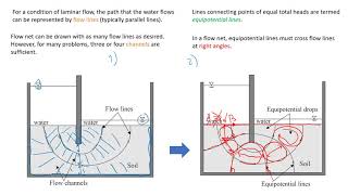
Correct. Flow lines indicate the direction of flow, while equipotential lines connect points of equal head. Remember, there can be no flow along an equipotential line because there is no hydraulic gradient.

So, how do these lines help us in calculations?
Good question! They form a flow net that can be used to visualize and calculate flow rates in different hydraulic conditions.

Can you give an example of where this applies?
Sure! It's often used in designing dams and understanding groundwater movement.
To summarize, flow lines show how water moves while equipotential lines show where it doesn’t move. They are both crucial for calculating flow rates.
Calculating Flow Rate
🔒 Unlock Audio Lesson
Sign up and enroll to listen to this audio lesson

Let’s now talk about how to calculate the flow rate. Who remembers the formula we use?
Is it ∆q = k * ∆h?
Exactly! Here, **k** represents the permeability of the material. Now, if we consider a field of length **L**, how do we determine the average hydraulic gradient?
I think it's the total head drop ∆h over the distance L?
Spot on! This gradient directly influences the flow rate as it provides the necessary driving force for the flow. Can anyone tell me how we get ∆h?
By looking at the difference in total head between two points?
Yes! You now understand how to connect these values in practical calculations. A good rule of thumb is to divide the total head change into equal segments to simplify your calculations.
What happens if we simplify too much?
That’s important to consider! Over-simplification might yield inaccurate results. Always keep in mind the context of your calculations.
In summary, flow rate depends on both the hydraulic gradient and the permeability of the material.
Using Flow Nets for Calculations
🔒 Unlock Audio Lesson
Sign up and enroll to listen to this audio lesson
Now that we've discussed flow rates, let’s talk about flow nets. How do we go about drawing one?
We draw equipotential and flow lines?
That's right! When we draw them, we want them to intersect neatly. Can anyone remind me the result of correctly drawn flow lines and equipotential lines?
It allows us to calculate the flow through a flow channel easier, right?
Exactly. And once you have that, breaking the overall head drop into **N** segments helps in managing more complex calculations. How do we mathematically express this?
I remember it’s ∆h = h / N?
Great! And from this, how do we compute the total flow rate?
We multiply k with the sum of flows across N segments?
Exactly! In summary, practicing with flow nets can significantly enhance your ability to understand and calculate groundwater flow.
Introduction & Overview
Read summaries of the section's main ideas at different levels of detail.
Quick Overview
Standard
In this section, we explore the process of calculating flow in a channel, introducing concepts such as equipotential lines and flow lines, which form flow nets. The section also emphasizes the significance of hydraulic gradients and provides a formula for determining flow rates through permeable media.
Detailed
Calculation of Flow in a Channel
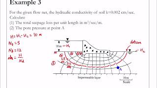
This section outlines the calculation of flow in a channel using hydraulic principles. It begins with the concept of equipotential lines, which represent points of equal total head, and flow lines, which show the direction of seepage down a hydraulic gradient. The notable point is that there can be no flow along an equipotential line, as it lacks a hydraulic gradient. The section then describes a specific field of length L within the flow channel and introduces the average hydraulic gradient as derived from the change in total head, ∆h.
Following this introduction, the section elaborates on creating flow nets. Notably, how sketching flow nets in curvilinear squares allows easier calculations, as a circle can be inscribed within the four-sided areas formed by flow and equipotential lines. The flow rate can then be calculated using a simplified relationship: ∆q = k * ∆h, where k is the permeability.
Finally, to compute the total flow rate, a complete flow net can be created, dividing the overall head drop h into N sections resulting in ∆h = h / N. This section encapsulates a crucial part of hydraulics, allowing for practical applications in engineering and environmental sciences.
Youtube Videos


Audio Book
Dive deep into the subject with an immersive audiobook experience.
Piezometers and Equipotential Lines
Chapter 1 of 5
🔒 Unlock Audio Chapter
Sign up and enroll to access the full audio experience
Chapter Content
If standpipe piezometers were inserted into the ground with their tips on a single equipotential line, then the water would rise to the same level in each standpipe. The pore pressures would be different because of their different elevations. There can be no flow along an equipotential line as there is no hydraulic gradient.
Detailed Explanation
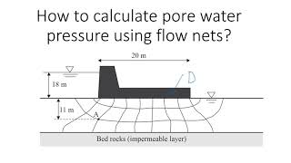
This chunk explains the purpose of standpipe piezometers and their relation to equipotential lines in the ground. When piezometers (short vertical tubes) are placed at the same level on an equipotential line, the water inside them will rise to the same height, indicating equal total head at that elevation. Although the pore pressures (the pressure of the water within the soil pores) may vary due to differing elevations of the piezometers, the key point is that no flow occurs along the equipotential line because there's no difference in hydraulic head (or gradient) along that line.
Examples & Analogies
Imagine a series of identical drinking straws placed in a glass of water at the same height. If you were to drink from each straw, the water level inside each would be the same due to the equal pressure exerted at that height, despite the fact the height from the bottom of the glass varies. This analogy highlights how pressure equilibrium leads to no flow when there's no gradient.
Flow Channel and Total Head Fall
Chapter 2 of 5
🔒 Unlock Audio Chapter
Sign up and enroll to access the full audio experience
Chapter Content
Consider a field of length L within a flow channel. There is a fall of total head ∆h. The average hydraulic gradient is As the flow lines are b apart and considering unit length perpendicular to field, the flow rate is.
Detailed Explanation
In this chunk, we examine a hypothetical field of length L within a flow channel where the total head decreases by a certain amount, denoted as ∆h. The concept of a hydraulic gradient, which is a measurement of how steeply the water flows from higher head to lower head, plays a critical role in understanding flow rates. The distance 'b' represents the spacing between flow lines. The flow rate can be calculated based on this hydraulic gradient and the characteristics of the flow channel.
Examples & Analogies
Think about a water slide at a park. The height of the starting point compared to the end defines how fast the water flows down. If the slide is steep (large gradient), the water rushes down quickly (high flow rate). If it is gentle (small gradient), the water flows more slowly (low flow rate). Similarly, the spacing between flow lines and the total head drop influences how fast groundwater moves through the soil.
Flow Nets and Curvilinear Squares
Chapter 3 of 5
🔒 Unlock Audio Chapter
Sign up and enroll to access the full audio experience
Chapter Content
There is an advantage in sketching flow nets in the form of curvilinear 'squares' so that a circle can be inscribed within each four-sided figure bounded by two equipotential lines and two flow lines.
Detailed Explanation
This chunk discusses the advantages of using curvilinear squares in drawing flow nets. The intention behind this is to simplify the representation of flow paths and head distribution in groundwater flow problems. By inscribing a circle within each 'square' formed by the intersection of equipotential and flow lines, we can visually and mathematically analyze the flow easier. It helps to understand how the flow behaves within a defined area, especially when assessing permeability and flow rates.
Examples & Analogies
Consider trying to fit a round pizza into a square box. In geometry, fitting shapes together can sometimes provide easier calculations for size and fit. Similar to how we look for convenient methods for packing, here, using curvilinear squares makes the analysis of complex flow systems simpler and more intuitive by providing consistent shapes for flow calculations.
Calculation of Flow Rate Through a Channel
Chapter 4 of 5
🔒 Unlock Audio Chapter
Sign up and enroll to access the full audio experience
Chapter Content
In such a square, b = L, and the flow rate is obtained as ∆q = k. ∆h. Thus the flow rate through such a flow channel is the permeability k multiplied by the uniform interval between adjacent equipotential lines.
Detailed Explanation
In this chunk, we derive the flow rate through a flow channel based on the permeability of the material (denoted as k) and the observed head drop (∆h). The basic relationship is established here: if the flow lines' spacing (b) equals the length of the field (L), we can use this to formulate the flow rate (∆q). This demonstrates how the properties of the soil or material affect the movement of water through it.
Examples & Analogies
Think about how quickly different types of soil absorb water. For instance, sand absorbs water faster because it has a higher permeability (k) than clay. If we pour the same amount of water (representing ∆h) onto both soils, the sand will allow water to flow through and away faster, resembling how we calculate flow rates in channels.
Total Flow Calculation
Chapter 5 of 5
🔒 Unlock Audio Chapter
Sign up and enroll to access the full audio experience
Chapter Content
For a complete problem, the flow net can be drawn with the overall head drop h divided into N so that ∆h = h / N. If N is the number of flow channels, then the total flow rate is.
Detailed Explanation
This final chunk outlines how to calculate the total flow through multiple channels in a flow net. It introduces a system where the overall head drop is divided into 'N' segments (representing the flow channels), allowing each segment's contribution to total flow to be assessed. Understanding this allows engineers and geologists to predict how water will move through an area more accurately, especially in practical situations such as engineering projects or environmental assessments.
Examples & Analogies
Imagine a series of connected water slides at a theme park, each representing a flow channel. If the total height of the slides is divided into sections, each section (N) contributes to how fast the people glide down (flow rate). By understanding how each slide works individually, the park engineers can better manage the overall flow of visitors, just as hydrogeologists manage water flow through soil.
Key Concepts
-
Flow Lines: Paths indicating the direction of fluid movement.
-
Equipotential Lines: Lines where total head remains constant.
-
Hydraulic Gradient: The ratio of the change in total head to the distance over which it falls.
-
Permeability: Material's ability to transmit fluid.
-
Flow Net: A graphical representation for analyzing flow.
Examples & Applications
In a dam, understanding how water moves through the soil layers is crucial for stability, represented by flow and equipotential lines.
Creating a flow net in groundwater studies helps estimate the amount of seepage and its effects on surrounding environments.
Memory Aids
Interactive tools to help you remember key concepts
Rhymes
In flow where rivers roam, the lines will find their home.
Stories
Imagine a wise old river that only flows in its path while resting over hills of equally high ground.
Memory Tools
Remember FLOW: F for Flow Lines, L for Lines Lay down the path of water, O for Observation of gradient, W for Water moves from high to low.
Acronyms
E-FLOW
for Equipotential
for Flow lines
for Lines of uniform head
for Optimal flow paths.
Flash Cards
Glossary
- Flow Line
A line that depicts the direction of flow within the channel.
- Equipotential Line
A line that connects points of equal hydraulic head.
- Hydraulic Gradient
The slope, or change in total head per unit length, driving fluid flow.
- Permeability (k)
A measure of a material's ability to allow fluids to pass through it.
- Flow Net
A diagram consisting of flow lines and equipotential lines used for hydraulic calculations.
- Field
The area bounded by two flow lines and two equipotential lines.
Reference links
Supplementary resources to enhance your learning experience.