
Flow Rate through Flow Channel
Enroll to start learning
You’ve not yet enrolled in this course. Please enroll for free to listen to audio lessons, classroom podcasts and take practice test.
Interactive Audio Lesson
Listen to a student-teacher conversation explaining the topic in a relatable way.
Calculating Flow Rate
🔒 Unlock Audio Lesson
Sign up and enroll to listen to this audio lesson

Now, let’s calculate flow rates in these channels! If we take a specific length L and measure a change in total head, what do we look for?

The average hydraulic gradient?
Exactly! Observing the rise in total head ∆h is key and we can define our average gradient accordingly. It leads us to the flow rate.

And what about the factors affecting that flow rate?
Great thought! It's related to permeability k and the distance between lines b. Together, we get the flow rate expressed as ∆q = k × ∆h.

Does that formula change when we have multiple flow channels?
Indeed! The overall flow will also depend on how we divide the total head. We can compute total flow as flow rates summed across all channels.

So, more channels mean better distribution of flow?
Precisely! Understanding these relationships is essential for engineers tasked with managing water flow through surfaces.
Introduction & Overview
Read summaries of the section's main ideas at different levels of detail.
Quick Overview
Standard
The section elaborates on the application of the Laplace Equation to determine flow rates through permeameters and describes flow nets as graphical solutions for two-dimensional seepage. It explains the significance of equipotential lines, flow lines, and the implications of hydraulic gradients in monitoring seepage behavior.
Detailed
Detailed Summary of Flow Rate through Flow Channel
This section covers the calculation of flow rate through a flow channel using the Laplace Equation.
For one-dimensional flow, integrating the Laplace Equation allows for the derivation of a general solution that accommodates specific boundary conditions, notably: at x = 0, the head h equals the height H, and at x = L, h equals 0. The result is a linear dissipation of head across the permeameter.
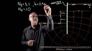
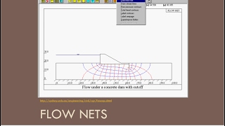
For two-dimensional flow, flow nets visually represent solutions with orthogonal intersecting equipotential and flow lines. These lines delineate the direction of flow and areas of constant total head. The section emphasizes how flow channels are formed between adjacent lines, and introduces practical observations using standpipe piezometers to measure hydraulic gradients.
As flow is computed through a specific field length L within a flow channel, it demonstrates that as total head drops ∆h, the flow rate can be systematically assessed. Labeled net calculations yield flow rates proportional to permeability, which can also be divided among multiple flow channels, yielding further insights into total flow. Overall, these principles are foundational in understanding seepage behavior through hydraulic structures.
Youtube Videos


Audio Book
Dive deep into the subject with an immersive audiobook experience.
Understanding Flow Nets
Chapter 1 of 4
🔒 Unlock Audio Chapter
Sign up and enroll to access the full audio experience
Chapter Content
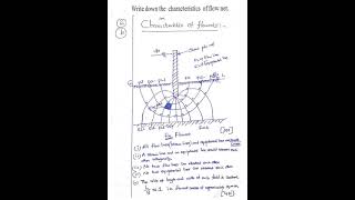
Flow Nets
Graphical form of solutions to Laplace equation for two-dimensional seepage can be presented as flow nets. Two orthogonal sets of curves form a flow net:
- Equipotential lines connecting points of equal total head h
- Flow lines indicating the direction of seepage down a hydraulic gradient
Detailed Explanation
Flow nets are graphical representations used in hydrology to solve the Laplace equation, particularly for two-dimensional seepage problems. They consist of two sets of lines:
1. Equipotential lines connect points that have the same total hydraulic head (h). These lines represent points where water pressure is equal, meaning no water will flow parallel to these lines since there's no difference in pressure.
2. Flow lines indicate the path that groundwater follows as it seeps through the soil. They show the direction of flow, which is always perpendicular to equipotential lines because flow occurs from high to low hydraulic head.
Moreover, two flow lines can never cross each other, and the same goes for equipotential lines. This ensures clarity in understanding the movement of water in the ground.
Examples & Analogies
Imagine a city map where certain streets are marked in blue (for flow lines) and others in green (for equipotential lines). The blue streets tell you where the traffic is going, while the green streets represent areas where there are equal traffic lights—meaning everything is flowing smoothly without any stops at those intersections. Just like drivers won't cross green lights at the same time, flow lines and equipotential lines maintain distinct paths without intersection.
Defining Flow Channels and Fields
Chapter 2 of 4
🔒 Unlock Audio Chapter
Sign up and enroll to access the full audio experience
Chapter Content
The space between two adjacent flow lines is known as a flow channel, and the figure formed on the flownet between any two adjacent flow lines and two adjacent equipotential lines is referred to as a field.
Detailed Explanation
A flow channel is defined as the space between two adjacent flow lines within a flow net. It represents the actual route that water takes through the soil, facilitating seepage from one location to another. The area enclosed by two flow lines and two equipotential lines is called a field. Each field signifies a distinct segment of flow, where we can analyze the head loss and determine how water moves through that section of soil. Thus, mapping out these fields allows hydrologists to model and predict the behavior of groundwater in a given area effectively.
Examples & Analogies
Think of a water slide at a water park. The slide's path (the flow channel) is defined by its boundaries. Each section of the slide, which corresponds to a ‘field,’ allows you to slide down from a height (equipotential line) directly to the pool below. The design of the slide ensures you follow a specific route, similar to how water moves through different channels in the ground.
Flow Rate Calculation
Chapter 3 of 4
🔒 Unlock Audio Chapter
Sign up and enroll to access the full audio experience
Chapter Content
Consider a field of length L within a flow channel. There is a fall of total head ∆h. The average hydraulic gradient is As the flow lines are b apart and considering unit length perpendicular to field, the flow rate is.
Detailed Explanation
In a flow channel, if we take a specific field of length L, we can measure how much water flows through it by examining how the total head (h) changes or drops, indicated as ∆h. The hydraulic gradient, which is the slope of the water table, is an important factor because it dictates how quickly water will flow through the soil. Hydrologists also consider the distance (b) between flow lines to determine flow rate, as closer lines mean faster flow. By calculating the average hydraulic gradient and applying appropriate formulas, we can express the flow rate in a way that accounts for the permeability of the soil.
Examples & Analogies
Imagine a long slide again, this time with varying heights at different intervals. The steepness (hydraulic gradient) of your slide dictates how quickly you slide down. The closer the intervals (flow lines) are, the faster you'd go. In this case, measuring the height drop over the slide (∆h) helps you calculate your potential speed (flow rate) during the ride.
Using Flow Nets for Total Flow Calculations
Chapter 4 of 4
🔒 Unlock Audio Chapter
Sign up and enroll to access the full audio experience
Chapter Content
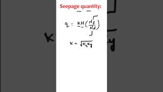
If N is the no. of flow channels, then the total flow rate is ...
Detailed Explanation
In a complete flow network, you can depict multiple flow channels, labeled as N. Each channel has its own head drop, and by dividing the total head drop (h) into smaller sections (∆h), this allows for a detailed calculation of flow rates across all channels. The total flow rate is essentially the sum of the flow rates of all individual channels. This cumulative approach provides comprehensive insight into how water moves through the entire system, giving hydrologists the data necessary to manage water resources effectively.
Examples & Analogies
Consider an airport with numerous runways, each runway representing a flow channel. Each runway has its own traffic, and figuring out how many planes land or take off (total flow) depends on the number of runways (N) and the traffic each runway handles. Just like breaking down total traffic into segments helps management, calculating total flow in a channel requires summing the flow from each part.