
Flow Nets
Enroll to start learning
You’ve not yet enrolled in this course. Please enroll for free to listen to audio lessons, classroom podcasts and take practice test.
Interactive Audio Lesson
Listen to a student-teacher conversation explaining the topic in a relatable way.
Introduction to Flow Nets
🔒 Unlock Audio Lesson
Sign up and enroll to listen to this audio lesson

Today, we're discussing flow nets, which are invaluable in visualizing two-dimensional seepage problems. Does anyone know what a flow net consists of?

I think it has flow lines and equipotential lines.
Exactly! Flow lines indicate the direction of seepage, while equipotential lines connect points of equal total head. This creates a structured network for analyzing flow.

"So, can these lines ever meet?
Calculations with Flow Nets
🔒 Unlock Audio Lesson
Sign up and enroll to listen to this audio lesson

Now that we understand what flow nets are, let’s dive into some calculations. Who can recall how we define the hydraulic gradient in a flow channel?
It’s the change in total head divided by the length of the channel, right?
That’s right! The hydraulic gradient helps us determine how steeply water will flow through the channel. Good memory! Now for practical calculations, if we set a field within a flow channel of length L, what defines the flow rate?
The flow rate equals the permeability times the head drop.
Precisely! With flow rate defined as q = k * Δh, we can visualize how the flow channels connect through the network. Remember that as we divide the head drop (h) across the number of flow channels (N), total flow can be expressed as q_total = k * (h/N).

I get it! Breaking it down into N channels helps us calculate the overall flow more easily.
Exactly! Flow nets make it easier to manage complex systems visually and mathematically.
Introduction & Overview
Read summaries of the section's main ideas at different levels of detail.
Quick Overview
Standard
This section introduces flow nets as a tool for visualizing and calculating two-dimensional flow and seepage. It explains the concepts of equipotential and flow lines, their interrelationships, and how flow channels and fields are formed. The section also discusses methods of calculating flow within these networks.
Detailed
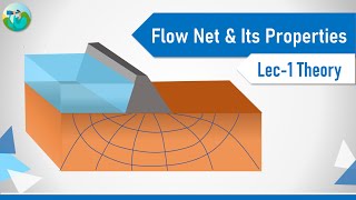
Flow Nets
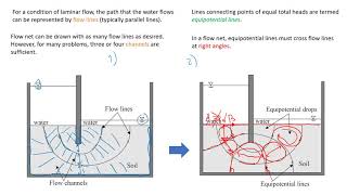
Flow nets are graphical forms used to provide solutions to the Laplace equation regarding two-dimensional seepage. They consist of two orthogonal sets of curves: equipotential lines, which connect points of equal total head, and flow lines, which illustrate the direction of seepage down a hydraulic gradient. An important aspect of flow nets is that two flow lines or equipotential lines can never intersect. The area between adjacent flow and equipotential lines is defined as a field.
In practical scenarios, for instance, when standpipe piezometers are placed on a single equipotential line, they will show the same water level, indicating the absence of hydraulic gradient (and thus, no flow) along that line. The hydraulic gradient across a field is defined by the change in total head ( eltah) over its length (L).
Additionally, flow nets can be efficiently represented using curvilinear squares so that a circle can fit inside each four-sided figure, making calculations more straightforward. For consistent flow calculated through these networks, we look at the permeability (k) multiplied by the head drop divided by the number of flow channels (N). Understanding flow nets is crucial in seepage analysis and hydraulic engineering applications.
Youtube Videos


Audio Book
Dive deep into the subject with an immersive audiobook experience.
Introduction to Flow Nets
Chapter 1 of 8
🔒 Unlock Audio Chapter
Sign up and enroll to access the full audio experience
Chapter Content
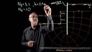
Graphical form of solutions to Laplace equation for two-dimensional seepage can be presented as flow nets. Two orthogonal sets of curves form a flow net:
Detailed Explanation
Flow nets are graphical representations that illustrate how water seeps through soil in two dimensions. They are formed using two sets of curves that are orthogonal, meaning they intersect at right angles. These curves help visualize the behavior of groundwater flow in various engineering problems.
Examples & Analogies
Imagine a map of a river system. The flow nets are like the paths that water would take as it travels through the landscape, represented by lines on the map corresponding to path options alongside rivers and streams.
Components of Flow Nets
Chapter 2 of 8
🔒 Unlock Audio Chapter
Sign up and enroll to access the full audio experience
Chapter Content
Equipotential lines connecting points of equal total head h and flow lines indicating the direction of seepage down a hydraulic gradient.
Detailed Explanation
In a flow net, equipotential lines are curves that connect points where the total hydraulic head is the same. These lines indicate where water pressure is equal. On the other hand, flow lines show the path that water takes as it seeps through the soil, indicating the direction of water flow based on the hydraulic gradient, which is the slope of the water table.
Examples & Analogies
Think of a water park slide. The slide's surface has different heights (like the equipotential lines), while the direction the water flows down the slide represents the flow lines. The slide’s gradient determines how quickly the water flows from the top to the bottom.
Flow and Equipotential Lines Do Not Cross
Chapter 3 of 8
🔒 Unlock Audio Chapter
Sign up and enroll to access the full audio experience
Chapter Content
Two flow lines can never meet and similarly, two equipotential lines can never meet.
Detailed Explanation
This principle is fundamental in hydraulic engineering. Flow lines and equipotential lines are distinct because they represent different aspects of water movement. If they were to cross, it would imply that there are simultaneous contradictory conditions for flow, which is not physically possible.
Examples & Analogies
Imagine two cars racing down a straight track; if they tried to occupy the same space at the same time, it would create a collision. Similarly, flow lines and equipotential lines must maintain their distinct paths without overlapping.
Flow Channels and Fields
Chapter 4 of 8
🔒 Unlock Audio Chapter
Sign up and enroll to access the full audio experience
Chapter Content
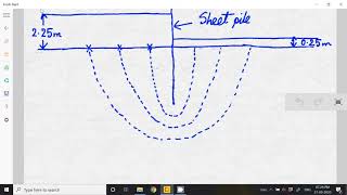
The space between two adjacent flow lines is known as a flow channel, and the figure formed on the flownet between any two adjacent flow lines and two adjacent equipotential lines is referred to as a field.
Detailed Explanation
Flow channels are the regions between two flow lines where the seepage occurs. The area bounded by two flow lines and two equipotential lines is known as a field, which helps in calculating flow characteristics effectively within that bounded area.
Examples & Analogies
Picture a series of streets (flow channels) and blocks (fields) in a neighborhood. The streets direct how cars travel, just like flow lines guide water, while each block represents a specific area of interest for the flow of water.
Measurement of Flow with Piezometers
Chapter 5 of 8
🔒 Unlock Audio Chapter
Sign up and enroll to access the full audio experience
Chapter Content
If standpipe piezometers were inserted into the ground with their tips on a single equipotential line, then the water would rise to the same level in each standpipe.
Detailed Explanation
Standpipe piezometers are instruments used to measure groundwater levels. When they are placed at the same altitude on an equipotential line, the water will rise to the same height in each piezometer, reflecting the equal hydraulic pressure at that level, even if the actual pore pressures differ due to elevation differences.
Examples & Analogies
Think of filling water in multiple connected bottles at the same height. Even though each bottle has its own shape (like varying elevations), water will adjust to the same level due to gravity acting uniformly, similar to the behavior observed in piezometers.
Calculating Flow Rates
Chapter 6 of 8
🔒 Unlock Audio Chapter
Sign up and enroll to access the full audio experience
Chapter Content
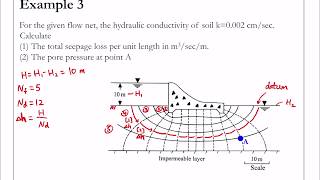
Consider a field of length L within a flow channel. There is a fall of total head ∆h. The average hydraulic gradient is... If N is the no. of flow channels, then the total flow rate is...
Detailed Explanation
To calculate flow rates, we consider the length and the hydraulic gradient in a flow channel. The fall in head (∆h) along these channels helps determine the average hydraulic gradient, which is critical for assessing how quickly water flows. The total flow rate can be summed up if we know the number of channels (N) involved in the seepage process.
Examples & Analogies
Imagine a system of highways with varying gradients leading down to a valley. The steeper the gradient (the higher the hydraulic gradient), the faster cars can travel down those highways. Similarly, in flow nets, the rate of water flow is directly related to the gradient.
Inscribing Circles in Flow Channels
Chapter 7 of 8
🔒 Unlock Audio Chapter
Sign up and enroll to access the full audio experience
Chapter Content
There is an advantage in sketching flow nets in the form of curvilinear 'squares' so that a circle can be inscribed.
Detailed Explanation
Sketching flow nets as curvilinear 'squares' allows for mathematics involving circles to be applied. Inscribing a circle ties geometry with fluid flow calculations, providing a simplified way to understand flow characteristics within the bounded area.
Examples & Analogies
Imagine shaping a round pizza into square slices. While the slices are straight-edged, the circular pizza helps conceptualize how it can be divided. In flow nets, inscribing circles within outlined channels simplifies complex calculations and visualizes flow patterns.
Calculating Total Flow
Chapter 8 of 8
🔒 Unlock Audio Chapter
Sign up and enroll to access the full audio experience
Chapter Content
For a complete problem, the flow net can be drawn with the overall head drop h divided into N so that ∆h = h / N.
Detailed Explanation
This step involves breaking the total head drop into multiple increments, enabling detailed calculations of flow through each discrete channel. By dividing the total head drop (h) by the number of flow channels (N), you establish a refined approach to calculate the total flow as it occurs.
Examples & Analogies
Consider a long staircase with several steps leading to the ground. Instead of jumping down all at once, breaking your descent into steps (N) helps you manage your progress more safely and with greater control, similar to how dividing head drops aids in flow calculations.
Key Concepts
-
Flow nets are graphical representations that include flow lines and equipotential lines.
-
Equipotential lines show equal total head while flow lines illustrate the direction of seepage.
-
No two flow or equipotential lines can intersect.
-
The area between flow and equipotential lines is called a field.
-
Flow rate is computed based on permeability and the change in head over the length of the field.
Examples & Applications
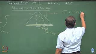
An embankment dam where water seepage can be analyzed using flow nets.
Calculation of flow rate in a flow channel based on measured hydraulic gradient.
Memory Aids
Interactive tools to help you remember key concepts
Rhymes
Flow lines flow, while heads show, in nets so bright, they guide our sight.
Stories
Imagine a town where water flows through a maze of streets. Each street represents a flow line, directing the water where it needs to go, while the landmarks along the way are the equipotential lines marking equal height.
Memory Tools
Remember: FLOW - 'Flow lines Offer Water' to help you recall the purpose of flow lines.
Acronyms
FLE - 'Flow = Lines and Equipotentials'. It summarizes the main components of flow nets.
Flash Cards
Glossary
- Flow Lines
Curves that indicate the direction of seepage in a flow net.
- Equipotential Lines
Curves that connect points of equal total head in a flow net.
- Hydraulic Gradient
The slope that represents the change in head over a distance in the direction of flow.
- Flow Channel
The space between two adjacent flow lines in a flow net.
- Field
The area bounded by two adjacent flow lines and two adjacent equipotential lines.
- Permeability (k)
A measure of how easily fluid can flow through soil or rock.
Reference links
Supplementary resources to enhance your learning experience.