
Calculation of Total Flow
Enroll to start learning
You’ve not yet enrolled in this course. Please enroll for free to listen to audio lessons, classroom podcasts and take practice test.
Interactive Audio Lesson
Listen to a student-teacher conversation explaining the topic in a relatable way.
Introduction to Flow Nets
🔒 Unlock Audio Lesson
Sign up and enroll to listen to this audio lesson

Today, we're discussing flow nets, which are crucial for visualizing seepage patterns in soil mechanics. Can anyone tell me what flow lines are?

Are flow lines the paths that water takes as it moves through the soil?
Exactly, Student_1! Flow lines indicate the direction of seepage. And what about equipotential lines?

These lines represent points of equal hydraulic head, right?
Correct! Now, remember, two flow lines can never intersect. Why do you think that is?

Because at the intersection, water would have to follow two different paths.
That's right! This non-intersecting behavior helps us form a clear flow net which simplifies our calculations significantly. Let’s summarize: flow lines show the flow direction, and equipotential lines show equal head levels.
Understanding Head Droppings
🔒 Unlock Audio Lesson
Sign up and enroll to listen to this audio lesson

Let's move on to head drop. Who can explain what ∆h represents?

It’s the difference in total head across a specific field length!
Exactly, Student_4! Now, if we divide the total head drop, h, into N parts, what would ∆h equal?
∆h would be h divided by N.
Correct! And this division is important for calculating flow. If we want to find the total flow rate through a flow channel, which key parameters do we need?
We need the permeability, k, and the spacing between the equipotential lines!
Wonderful! So, the total flow rate can be expressed as k multiplied by this spacing. Let’s recap: ∆h describes head drop, and dividing it by N gives clarity on flow distribution.
Calculating Total Flow
🔒 Unlock Audio Lesson
Sign up and enroll to listen to this audio lesson
Now we’ll apply everything. When calculating total flow, what formula arises from our previous discussions?
Is it... the total flow rate equals k times the spacing between equipotential lines?
Yes, that's one part of it! We also factor in ∆h. The overall flow is a function of the total head drop divided by the number of flow channels. Can anyone sketch a simple flow net based on these parameters?
Sure! I can draw it right now.
Excellent! This sketching is crucial because it helps visualize the problem. Recap for us: what do we consider when we calculate total flow?
We consider the permeability, the spacing between equipotential lines, and the head drop.
Correct! Understanding these relationships is key to mastering fluid flow in permeameters.
Introduction & Overview
Read summaries of the section's main ideas at different levels of detail.
Quick Overview
Standard
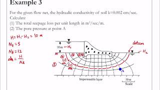
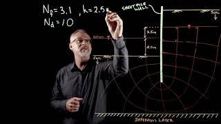
In this section, the focus is on how to calculate the total flow in permeameters through specific methods involving flow nets and the Laplace equation. Key concepts include the derivation of flow rates and the relationship between total head drop and the number of flow channels.
Detailed
Calculation of Total Flow
In this section, we explore the method of calculating total flow in a permeameter by utilizing the Laplace equation. The basic premise revolves around establishing a flow net which is essential for determining seepage patterns and flow rates in two-dimensional scenarios. Key concepts include the relationship between hydraulic gradients, head drops, and the number of flow channels.
Key Concepts:
- Flow Nets: These are graphical solutions to the Laplace equation, representing two orthogonal sets of curves: the equipotential lines (connecting points of equal total head) and the flow lines (showing the direction of seepage).
- Total Head Drop (∆h): The difference in head within a flow channel, essential for calculating flow rates.
- Flow Channels: Areas between flow lines where water flows, and these are defined by the spacing of equipotential lines.
Total Flow Calculation:
To find the total flow, one must first divide the head drop (h) across the length of the field into N intervals, where ∆h is defined as h/N. Subsequently, using the established relationships, the total flow rate can be computed by factoring the permeability (k) and the spacing of the equipotential lines, yielding a practical solution for flows in various contexts.
Youtube Videos


![Basic Geotechnical Engineering [ 15cv45]](https://img.youtube.com/vi/JcLtXblqqGg/mqdefault.jpg)


Audio Book
Dive deep into the subject with an immersive audiobook experience.
Flow Net Division
Chapter 1 of 2
🔒 Unlock Audio Chapter
Sign up and enroll to access the full audio experience
Chapter Content
For a complete problem, the flow net can be drawn with the overall head drop h divided into N so that ∆h = h / N.
Detailed Explanation
In this first step of calculating total flow, we begin by considering the entire flow net, which is a graphical representation of the flow paths of liquid through a porous medium. We divide the total head drop (denoted as 'h') into 'N' equal segments. This means the change in head (∆h) across each segment is calculated by taking the total head and dividing it by the number of segments. Essentially, we are simplifying the problem by breaking it down into smaller, easier-to-manage parts.
Examples & Analogies
Imagine you are reading a large book with many chapters. To make it more manageable, you decide to read one chapter at a time. The total number of pages in the book represents the total head (h), and each chapter represents a segment (N). Just like dividing the book makes it easier to read, dividing the total head makes it easier to calculate the flow.
Calculating Total Flow Rate
Chapter 2 of 2
🔒 Unlock Audio Chapter
Sign up and enroll to access the full audio experience
Chapter Content
If N is the no. of flow channels, then the total flow rate is.
Detailed Explanation
Once we have established the number of segments (N), each representing a flow channel, we can proceed to calculate the total flow rate. The total flow rate can be thought of as the sum of the flow rates through each of those individual channels. The concept here is to take into account all the separate paths that the fluid is taking through the permeable material and to add those contributions together. This total gives us an overall understanding of how much fluid is moving through the system in a given time frame.
Examples & Analogies
Consider a network of rivers flowing into a larger lake. Each river represents a flow channel (N), and the total amount of water that flows into the lake is the total flow rate. Just like we can combine the water flow from each river to understand how much water enters the lake, we can sum the flow rates from all channels to find the total flow rate in a permeable material.
Key Concepts
-
Flow Nets: These are graphical solutions to the Laplace equation, representing two orthogonal sets of curves: the equipotential lines (connecting points of equal total head) and the flow lines (showing the direction of seepage).
-
Total Head Drop (∆h): The difference in head within a flow channel, essential for calculating flow rates.
-
Flow Channels: Areas between flow lines where water flows, and these are defined by the spacing of equipotential lines.
-
Total Flow Calculation:
-
To find the total flow, one must first divide the head drop (h) across the length of the field into N intervals, where ∆h is defined as h/N. Subsequently, using the established relationships, the total flow rate can be computed by factoring the permeability (k) and the spacing of the equipotential lines, yielding a practical solution for flows in various contexts.
Examples & Applications
If a permeameter shows a total head drop of 10 m across 5 flow channels, with a permeability of 2 m/s, the total flow rate would be calculated as: q = k * (Δh / N) = 2 * (10 / 5) = 4 m³/s.
In a field of length 20 m where equipotential lines are spaced every 2 m, and total head drop is 8 m, the total flow rate k can be deduced by measuring the hydraulic gradient.
Memory Aids
Interactive tools to help you remember key concepts
Rhymes
Head drop low, flow will show, equipotential lines will guide the flow.
Stories
Imagine a water park where the slides represent flow lines, and the kiddie pool represents equipotential lines; water flows down the longest slide but never crosses the kiddie pool.
Memory Tools
F.E.L.D. - Flow Lines, Equipotential Lines, Drop - remember the concepts.
Acronyms
HEFT - Head, Equipotential, Flow, Total - key concepts to remember.
Flash Cards
Glossary
- Flow Net
A graphical representation of the flow of water through soil in terms of flow lines and equipotential lines.
- Equipotential Lines
Lines that connect points of equal hydraulic head in a flow net.
- Flow Lines
Lines indicating the path water takes as it flows through soil, perpendicular to equipotential lines.
- Total Head Drop (∆h)
The difference in total hydraulic head experienced through a flow channel.
- Permeability (k)
A measure of how easily water can flow through soil or rock, affecting flow rate calculations.
- Hydraulic Gradient
The slope of the water table or piezometric surface, indicating the driving force of seepage.
- Flow Rate
The volume of water flowing through a section over a specific time, critical for engineering applications.
Reference links
Supplementary resources to enhance your learning experience.