
Design Features of Through-Hole Packaging
Interactive Audio Lesson
Listen to a student-teacher conversation explaining the topic in a relatable way.
Long Component Leads
🔒 Unlock Audio Lesson
Sign up and enroll to listen to this audio lesson

Today we're discussing through-hole packaging, starting with a key feature: long component leads. Can anyone tell me why these leads are important?

I think they allow the components to stick out the other side of the PCB for better connection?
Exactly! The long leads enable easy soldering on the underside, which reinforces mechanical connections. Remember, longer leads also allow for simple modifications if needed.

Does this mean they are easier to replace?
Yes! These leads facilitate repairability because they are visible and accessible. This leads us to remember that L.E.A.D stands for 'Long Ease of Access and Durability'.

That’s a neat acronym!
Let’s summarize: We discussed long leads as critical for soldering and repairability. Great job, everyone!
Size and Profile of Components
🔒 Unlock Audio Lesson
Sign up and enroll to listen to this audio lesson

Now let's discuss the size and profile of through-hole components. Why do these traits matter?

Their bulk could take up too much space, right?
Correct. The larger size can limit component density on the PCB, making the overall design bulkier. Imagine a crowded city versus a spacious one.
But larger components might be stronger, right?
Absolutely! Higher profiles often correlate with enhanced durability, suitable for robust applications. So, what can we remember? H.I.G.H for High profile Indicates Greater Hardiness!
I love that! H.I.G.H for the win!
Final takeaway: Sizes affect component layout and strength in through-hole designs. Ready for our next topic?
Applications of Through-Hole Packaging
🔒 Unlock Audio Lesson
Sign up and enroll to listen to this audio lesson
Let's shift to applications of through-hole packaging. Who can suggest where we might commonly see these?
I heard they are good for military applications because of their strength.
Spot on! They excel in high-stress environments like military electronics and power supplies. Their durability is crucial.
What about prototypes? Can we use them there?
Absolutely! Prototyping benefits from through-hole because of manual soldering ease and flexibility to make changes. Now, our mnemonic is P.O.W.E.R: Prototypes Often Won't easily Eliminate Repairs!
That’s a pretty meaningful acronym!
Great discussion, everyone! Remember, through-hole packaging strengthens prototypes and military devices due to durability.
Introduction & Overview
Read summaries of the section's main ideas at different levels of detail.
Quick Overview
Standard
Through-hole packaging is characterized by long component leads, larger sizes, and higher profiles compared to surface mount packages. These features contribute to its reliability in mechanical strength, making it suitable for specific applications, though it has downsides in size and assembly speed.
Detailed
Design Features of Through-Hole Packaging
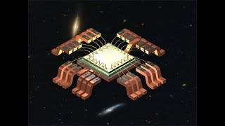
Through-hole packaging remains a vital choice in semiconductor device manufacturing. This method allows components to be inserted into holes drilled through the PCB, with long metal leads being soldered on the opposite side. Key design features include:
- Long Component Leads: These contribute to effective soldering on the underside of the PCB and facilitate easy reconnectivity and repair.
- Large Size: Typically, through-hole components are bulkier than surface-mount alternatives, which can limit spatial efficiency.
- Higher Profile: The vertical space occupation by through-hole components is more significant, impacting design layouts for compact electronics.
The associated mechanical durability and ease of manual soldering make through-hole an attractive option in applications where reliability is crucial, despite larger size and longer assembly times.
Youtube Videos

Audio Book
Dive deep into the subject with an immersive audiobook experience.
Long Component Leads
Chapter 1 of 3
🔒 Unlock Audio Chapter
Sign up and enroll to access the full audio experience
Chapter Content
● Long Component Leads: Components have long metal leads that pass through the PCB and are soldered on the opposite side.
Detailed Explanation
In through-hole packaging, components come with long metal leads. These leads are designed to be inserted through appropriately drilled holes in the printed circuit board (PCB). Once the leads are on the other side of the PCB, they are soldered in place. The length of the leads allows for strong connections and provides a robust anchor point, which is crucial in environments where stability and strength are paramount.
Examples & Analogies
Think of how a nail is used to hold two pieces of wood together. The longer the nail, the deeper it can penetrate into the wood, creating a stronger bond. Similarly, long leads in through-hole components provide a deep connection with the PCB, ensuring that the component remains secured.
Large Size
Chapter 2 of 3
🔒 Unlock Audio Chapter
Sign up and enroll to access the full audio experience
Chapter Content
● Large Size: Through-hole components are typically larger and bulkier compared to surface-mount counterparts.
Detailed Explanation
Through-hole components are generally larger than their surface-mount counterparts. This bulkiness can be attributed to the need for long leads and the design of the components themselves. While larger components can offer several advantages, including ease of handling and stability, they also occupy more space on the PCB, which might limit the overall component density.
Examples & Analogies
Imagine trying to fit large boxes into a small closet. The larger the boxes, the fewer you can fit in that space. Similarly, the size of through-hole components can limit the number of components that can be placed on a PCB.
Higher Profile
Chapter 3 of 3
🔒 Unlock Audio Chapter
Sign up and enroll to access the full audio experience
Chapter Content
● Higher Profile: The height of the component is greater, leading to larger vertical dimensions on the PCB.
Detailed Explanation
Through-hole components tend to be taller than surface-mount components, leading to a higher profile on the PCB. This added height can influence the overall design of the circuit board, especially in compact electronic devices where space is at a premium. The greater vertical dimensions may necessitate additional considerations for fitting within enclosures or interacting with other components on the board.
Examples & Analogies
Consider building a city with different building heights. Taller buildings may require more space between them to ensure they don't overshadow shorter buildings. Similarly, the taller profile of through-hole components can dictate how they are arranged on the PCB and how close other components can be placed.
Key Concepts
-
Long Component Leads: Facilitate effective soldering and increased repairability.
-
Larger Size: Limits the density of components on a PCB, affecting design efficiency.
-
Higher Profile: Provides greater mechanical strength but increases space usage.
Examples & Applications
A typical application for through-hole packaging is in high-current applications like power supplies, where durability is critical.
In prototype development, engineers favor through-hole packaging for its ease in manual soldering.
Memory Aids
Interactive tools to help you remember key concepts
Rhymes
Long leads for soldering ease, stronger connections, if you please.
Stories
Imagine a busy street where taller buildings, like through-hole components, take up more ground, offering more strength but crowding the space more.
Memory Tools
H.I.G.H: Higher profile Indicates Greater Hardiness!
Acronyms
P.O.W.E.R
Prototypes Often Won't easily Eliminate Repairs!
Flash Cards
Glossary
- ThroughHole Packaging
A method where components have long leads inserted through the PCB and soldered on the opposite side.
- Component Leads
Metal leads that connect electronic components to the PCB.
- Mechanical Strength
The ability of a component to withstand stress without breaking.
- Profile
The height of the component when mounted on the PCB.
Reference links
Supplementary resources to enhance your learning experience.