
Lab Work on Voltage Regulators
Interactive Audio Lesson
Listen to a student-teacher conversation explaining the topic in a relatable way.
Overview of Linear Voltage Regulators
🔒 Unlock Audio Lesson
Sign up and enroll to listen to this audio lesson

Today we will discuss linear voltage regulators, a crucial component in stabilizing power supplies. Can anyone tell me why having a constant voltage is important?

It's important because many electronic components need a stable voltage to function properly.
That's correct! We want to avoid fluctuations that could damage sensitive devices. Now, what components do you think we need to build a simple regulator circuit?

We'll need an Op-Amp and a pass transistor!
Exactly! The Op-Amp will control the transistor to ensure the voltage remains stable at 5V. Let's talk more about how we would set up our circuit.
Materials Required
🔒 Unlock Audio Lesson
Sign up and enroll to listen to this audio lesson

For our voltage regulator, we need specific materials. Who remembers the components we listed?

We need an Op-Amp, a pass transistor, a Zener diode, and some resistors and capacitors.
Great recall! The Zener diode will maintain a reference voltage, which is critical. What do you think the resistors and capacitors will do in our circuit?

They help stabilize the output and ensure proper functioning of the Op-Amp!
Correct! They also help filter out noise. Now, let’s transition to how we will actually build the circuit.
Circuit Construction Procedure
🔒 Unlock Audio Lesson
Sign up and enroll to listen to this audio lesson
Let's dive into the procedure for constructing the circuit. The first step is to connect the Op-Amp and the pass transistor. Can anyone guide the first few steps?
We start with connecting the Op-Amp's input to our reference voltage through the Zener diode.
Correct! Then, we connect the output of the Op-Amp to the base of our pass transistor to control the output voltage. What happens when we apply a varying input voltage?
The Op-Amp adjusts the base voltage of the transistor so that the output stays at 5V!
Exactly right! Now let’s discuss what to measure once we have our circuit up and running.
Testing the Output Voltage
🔒 Unlock Audio Lesson
Sign up and enroll to listen to this audio lesson
After constructing our circuit, we need to test it. Why do you think this step is critical?
To ensure that it stabilizes the output voltage as intended!
Yes! Testing with varying input voltages and load conditions allows us to verify performance. How would you approach measuring the output?
I would use a multimeter to check if it consistently reads 5V.
Exactly! Good work everyone. This testing will confirm our regulator is effective.
Introduction & Overview
Read summaries of the section's main ideas at different levels of detail.
Quick Overview
Standard
The section outlines the objectives and procedures involved in building a linear voltage regulator circuit with a specific output voltage of 5V. It includes a list of necessary materials and a step-by-step guide to constructing the circuit, applying a variable input voltage, and testing the output under varying load conditions.
Detailed
Lab Work on Voltage Regulators
This section provides a practical approach to the understanding and construction of a linear voltage regulator circuit using an operational amplifier (Op-Amp) and a pass transistor. The main objective is to maintain a constant output voltage of 5V regardless of input voltage variations or load changes, which is crucial for stable electronic device operations.
Objective
The goal is to design and construct a circuit that can consistently deliver a stable voltage output despite fluctuations in input or load conditions.
Materials Needed
- Op-Amp (e.g., LM741)
- Pass transistor (e.g., 2N2222)
- Zener diode for voltage reference
- Resistors and capacitors for circuit stability
- Power supply and multimeter for testing
Procedure
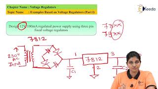
- Circuit Construction: Start by creating the voltage regulator circuit, integrating the Op-Amp, pass transistor, and Zener diode to establish the reference voltage.
- Applying Varying Input Voltages: Attach a variable input voltage to the circuit and utilize a multimeter to monitor the output voltage.
- Testing Load Currents: Test the regulator under different load currents to evaluate its ability to maintain the output at 5V consistently. This step is critical in ensuring that the regulator works effectively in real-world conditions.
Through this lab work, students will gain practical skills in building voltage regulator circuits and understanding their significance in electronic applications.
Youtube Videos


Audio Book
Dive deep into the subject with an immersive audiobook experience.
Objective of the Lab Work
Chapter 1 of 3
🔒 Unlock Audio Chapter
Sign up and enroll to access the full audio experience
Chapter Content
- Objective: Build a linear voltage regulator using an Op-Amp and pass transistor to maintain a constant 5V output.
Detailed Explanation
The objective of this lab work is to design and construct a linear voltage regulator circuit. This circuit will use an operational amplifier (Op-Amp) along with a pass transistor. The aim is to achieve a stable output voltage of 5V, which means that no matter how the input voltage varies, the output should remain steady at 5V. This is crucial because stable voltage is needed to power sensitive electronics effectively.
Examples & Analogies
Think of it like adjusting the temperature in a room with a thermostat. Just as a thermostat measures the room temperature and adjusts the heating system to keep it consistent, the voltage regulator measures the output voltage and adjusts the power supply to maintain a steady 5V output.
Materials Required
Chapter 2 of 3
🔒 Unlock Audio Chapter
Sign up and enroll to access the full audio experience
Chapter Content
- Materials:
- Op-Amp (e.g., LM741)
- Pass transistor (e.g., 2N2222)
- Zener diode for voltage reference
- Resistors, capacitors
- Power supply and multimeter
Detailed Explanation
In this segment, several materials needed for the lab are listed. The key components are:
- Op-Amp (like LM741): This acts as the brain of the regulator, processing the input voltage and ensuring the output stays constant.
- Pass transistor (such as 2N2222): This component is crucial for controlling the output voltage. It regulates how much current flows based on the signals received from the Op-Amp.
- Zener diode: This component provides a stable reference voltage, essential for the circuit’s function.
- Resistors and capacitors: These devices help in fine-tuning the circuit's behavior and stability.
- Power supply and multimeter: The power supply provides the input voltage, while the multimeter is used to measure voltage levels throughout the testing process.
Examples & Analogies
Imagine baking a cake. Each ingredient serves a specific purpose: flour gives structure, sugar adds sweetness, eggs provide binding. Similarly, each component listed here plays a critical role in ensuring the voltage regulator works properly.
Building the Circuit
Chapter 3 of 3
🔒 Unlock Audio Chapter
Sign up and enroll to access the full audio experience
Chapter Content
- Procedure:
- Construct the voltage regulator circuit with the Op-Amp and pass transistor.
- Apply a variable input voltage and measure the output voltage to ensure it remains stable at 5V.
- Test the regulator with different load currents and verify its ability to maintain the output voltage.
Detailed Explanation
The lab procedure starts with constructing the voltage regulator circuit. First, you will connect the Op-Amp and pass transistor according to the design. Once assembled, you will gradually increase the input voltage and observe the output voltage. The goal is to confirm it stays at 5V despite changes in input. Finally, you will apply different loads to this circuit to see how well it maintains the output voltage under varying conditions, which simulates real-world usage where devices require fluctuating power.
Examples & Analogies
This is similar to running a marathon. Just as a runner must maintain a steady pace while adapting to different terrains (like uphill or downhill), the voltage regulator must adapt to varying input voltages while keeping the output steady.
Key Concepts
-
Voltage Stability: Maintaining a constant voltage output is essential for the reliable operation of electronic devices.
-
Op-Amp Functionality: The Op-Amp plays a central role in regulating the output voltage by comparing it to a reference voltage.
-
Testing Procedure: Proper testing ensures that the voltage regulator functions as intended across varying loads and input voltages.
Examples & Applications
An LM741 Op-Amp is used in a circuit to regulate a power supply for a microcontroller, ensuring that the microcontroller receives a stable 5V.
A Zener diode maintains a voltage reference in the circuit, allowing the Op-Amp to create a robust feedback loop.
Memory Aids
Interactive tools to help you remember key concepts
Rhymes
In circuits where the charge flows, keep voltages steady, that’s how it goes.
Stories
Imagine a gardener (Op-Amp) who waters plants (voltage) with a hose (transistor), ensuring each plant receives just the right amount, regardless of weather conditions (input variations).
Memory Tools
RAP: Regulator, Adjustment, and Pass; the key concepts of voltage regulation.
Acronyms
VREG
Voltage Regulation Ensures Stability.
Flash Cards
Glossary
- Linear Voltage Regulator
A circuit that maintains a constant output voltage regardless of input voltage variations.
- OpAmp
Operational amplifier, a fundamental building block in analog electronics used to amplify voltage signals.
- Pass Transistor
A transistor that controls the output voltage in a voltage regulator circuit.
- Zener Diode
A diode that allows current to flow in the reverse direction when a specific voltage is reached, used for voltage reference.
- Multimeter
An instrument used to measure voltage, current, and resistance in electrical circuits.
Reference links
Supplementary resources to enhance your learning experience.