
Op-Amp Applications III - Comparators and Voltage Regulators
Interactive Audio Lesson
Listen to a student-teacher conversation explaining the topic in a relatable way.
Introduction to Comparators
🔒 Unlock Audio Lesson
Sign up and enroll to listen to this audio lesson

Today, we will discuss comparators. Can someone tell me what a comparator does in simple terms?

Is it something that compares two voltages?
Exactly! A comparator compares two input voltages. If the voltage at the non-inverting input is greater than the inverting input, the output is high. This means it can switch between high and low based on voltage comparisons.

What does it mean to have a high or low output?
Great question! A high output usually means it's in a logic '1' state, and a low output is a logic '0'. This feature is fundamental for digital circuits.

Are there any applications for comparators?
Yes, there are many! For example, comparators are used in zero-crossing detection for waveform analysis. Remember, think of a comparator like a light switch that turns on when the voltage rises above a certain threshold.
To summarize, comparators take in two voltages and produce an output based on which is greater, making them crucial in digital systems.
Hysteresis in Comparators
🔒 Unlock Audio Lesson
Sign up and enroll to listen to this audio lesson

Now, let’s talk about hysteresis. Why do you think it's important in comparators?

Maybe to avoid false switching?
Exactly! Hysteresis introduces a small threshold that helps prevent noise from causing unwanted switching of the output. When the input voltage is close to the threshold, the output remains stable until a significant change occurs.
How do we design a comparator with hysteresis?
We add a positive feedback loop from the output to the inverting input, which creates the voltage thresholds necessary for hysteresis. This way, it only switches outputs when the input crosses set points.
In summary, hysteresis is critical for comparator designs to ensure reliable operation under varying input conditions.
Voltage Regulator Design
🔒 Unlock Audio Lesson
Sign up and enroll to listen to this audio lesson
Let's explore voltage regulators. Can someone explain what a voltage regulator does?
It keeps the output voltage stable, right?
Correct! Voltage regulators ensure that the output voltage remains constant regardless of changes in input voltage or load conditions. Why is this so important?
Because some devices need a stable voltage to function correctly?
Absolutely! Sensitive electronics require stable voltages to prevent malfunction. Now, let's discuss the basic design of a linear voltage regulator.
What components do we need for that?
You typically need a pass element like a transistor, a voltage reference, and of course, the op-amp in the feedback loop. The op-amp compares the output voltage to this reference voltage.
In summary, linear regulators are essential for providing stable outputs, and their design involves a feedback mechanism utilizing an op-amp.
Switching Voltage Regulators
🔒 Unlock Audio Lesson
Sign up and enroll to listen to this audio lesson
Now, let’s switch gears and talk about switching voltage regulators. How do these differ from linear ones?
I think they are more efficient?
Right again! Switching regulators are more efficient because they switch the input voltage on and off rapidly, reducing energy loss. But they are also more complex. Can you name the types of switching regulators?
There’s the buck converter and the boost converter, right?
Perfect! Buck converters step down the voltage, while boost converters step it up. Switching regulators also use inductors and capacitors to achieve their objectives.
In summary, switching voltage regulators are efficient and versatile but come with complexity in their designs.
Introduction & Overview
Read summaries of the section's main ideas at different levels of detail.
Quick Overview
Standard
In this section, we explore op-amp comparators and voltage regulators. Comparators are circuits that compare two input voltages to produce a digital output, while voltage regulators maintain a constant output voltage. We discuss design considerations, hysteresis in comparators, and stability techniques essential for reliable performance in electronic systems.
Detailed
Op-Amp Applications III - Comparators and Voltage Regulators
This section delves into the design and application of comparators and voltage regulators, two critical functionalities of operational amplifiers. Comparators are used to compare two input voltages, providing a digital high or low output based on this comparison, making them vital in digital systems and signal processing. Key attributes include their operation in open-loop configurations and the introduction of hysteresis to prevent erratic switching. Various applications, such as zero-crossing detection and pulse width modulation, are discussed.
On the other hand, voltage regulators provide a stable output voltage vital for powering sensitive electronics. Two main types of regulators are explored:
- Linear Voltage Regulators: Using a feedback mechanism to maintain constant voltage despite changes in input or load.
- Switching Voltage Regulators: More efficient, they switch the input voltage on and off to achieve a stable output.
We also emphasize the significance of stability and compensation techniques that ensure reliable voltage regulation. The section concludes with practical lab work related to building and testing regulators and comparators, illustrating their real-world applications.
Youtube Videos


Audio Book
Dive deep into the subject with an immersive audiobook experience.
Introduction to Comparators and Voltage Regulators
Chapter 1 of 13
🔒 Unlock Audio Chapter
Sign up and enroll to access the full audio experience
Chapter Content
In this chapter, we will explore the design and analysis of comparators and voltage regulators, two essential applications of operational amplifiers (Op-Amps). These circuits are widely used in many electronic systems, from digital logic to power supply systems.
● Comparators: Circuits that compare two input voltages and produce a digital high or low output based on the comparison.
● Voltage Regulators: Circuits designed to maintain a constant output voltage, ensuring stable power supply to sensitive electronic devices.
We will discuss their operation, design considerations, and stability techniques that ensure reliable performance in various applications.
Detailed Explanation
This chunk introduces two main applications of operational amplifiers: comparators and voltage regulators. Comparators compare two input voltages and output either a high or low signal based on which input is greater, often used in digital circuits. In contrast, voltage regulators provide a steady output voltage even when input voltage or load varies, critical for sensitive electronics. The chapter promises to dive into how these devices work, their design factors, and methods to ensure they perform reliably across different situations.
Examples & Analogies
Think of comparators as decision-makers, like a judge deciding if a contestant's score is above or below a certain threshold. If skilled enough to cross the threshold, they receive a 'yes' (logic high) or 'no' (logic low) response. Voltage regulators can be likened to a thermostat in your home; regardless of outside temperature changes, it keeps the room temperature steady and comfortable, ensuring that electronic devices operating in varied conditions maintain their required performance.
Op-Amp Comparators
Chapter 2 of 13
🔒 Unlock Audio Chapter
Sign up and enroll to access the full audio experience
Chapter Content
A comparator is a circuit that compares two voltages and produces an output depending on the relative values of these voltages. The output is a high or low digital signal, making comparators ideal for digital decision-making circuits.
Detailed Explanation
This section defines a comparator as a special type of circuit whose purpose is to compare two different voltages. The result of this comparison is a digital output that can signal whether one voltage is higher or lower than the other. This binary nature (high or low) allows comparators to be pivotal in digital systems, where such decisions are vital for processing signals correctly.
Examples & Analogies
Imagine a light switch responsible for turning a light on or off based on whether the room is dark or bright. The switch only responds to the light level and makes a definitive decision to either illuminate or not, similar to how a comparator evaluates voltages to provide a high or low signal.
Comparator Design
Chapter 3 of 13
🔒 Unlock Audio Chapter
Sign up and enroll to access the full audio experience
Chapter Content
● Basic Comparator Circuit:
○ The comparator is typically an Op-Amp without feedback, allowing it to operate in an open-loop configuration.
○ The non-inverting input (+) receives one signal, while the inverting input (-) receives the other.
○ When the voltage at the non-inverting input exceeds that of the inverting input, the output is high; otherwise, it is low.
● Output Behavior:
○ If V+>V−, the output switches to the positive supply voltage (logic high).
○ If V+
Detailed Explanation
In designing a comparator circuit, we typically use an operational amplifier (Op-Amp) without any feedback, which allows for its open-loop functionality. In this setup, the non-inverting input receives one voltage and the inverting input receives another. If the voltage at the non-inverting input surpasses that of the inverting input, the output generates a high signal; conversely, if it's lower, the output becomes a low signal. This clear cut behavior helps in creating digital outputs that can be used in various applications.
Examples & Analogies
Think of this setup like a scale that determines if you weigh above or below a specific value. You place objects on one side (non-inverting input) and compare it against a fixed weight (inverting input). If the added weight exceeds the comparison weight, the output (response) indicates 'heavier' (high), otherwise it indicates 'lighter' (low).
Hysteresis in Comparators
Chapter 4 of 13
🔒 Unlock Audio Chapter
Sign up and enroll to access the full audio experience
Chapter Content
● Purpose: To avoid erratic switching due to noise or small fluctuations at the input, hysteresis is often introduced into comparators. Hysteresis creates a small threshold between the switching points.
● Design: Hysteresis is implemented by introducing a small positive feedback loop from the output to the inverting input, raising the threshold for switching.
Detailed Explanation
Hysteresis is a technique employed in comparators to stabilize their output against noisy input signals, which can cause erratic changes in output. By creating a small range between the thresholds for switching from high to low or vice versa, hysteresis ensures that minor fluctuations don’t incorrectly trigger an output change. This is achieved by incorporating feedback from the output back to the inverting input, thus making the transition point less susceptible to noise.
Examples & Analogies
Consider a thermostat that only turns the heating on after the temperature drops below a certain point and only switches off after it surpasses another, slightly higher point. This range ensures that small day-to-day temperature variations don’t cause the heater to turn on and off rapidly, providing a smooth and stable heat output, similar to hysteresis preventing frequent toggling in comparators.
Comparator Applications
Chapter 5 of 13
🔒 Unlock Audio Chapter
Sign up and enroll to access the full audio experience
Chapter Content
● Zero Crossing Detection: Used in waveform generators and signal processing to detect when a waveform crosses a threshold, indicating the start of a new cycle.
● Pulse Width Modulation (PWM): In PWM applications, comparators compare a reference waveform (e.g., a sawtooth wave) with a control signal to generate a pulse of varying width.
● Level Shifting: Comparators are used to shift a signal from an analog range to a digital range (e.g., threshold detection).
Detailed Explanation
Comparators find a wide range of applications in electronic systems. One important use is in zero crossing detection, where it identifies when an AC waveform crosses a defined level—critical for many signal processing tasks. They are also instrumental in pulse width modulation (PWM), where they help modulate signals for controlling power devices by adjusting the width of pulses. Lastly, comparators assist in level shifting, allowing the smooth transition from analog variations to defined digital states, thus facilitating improved digital logic performance.
Examples & Analogies
Think of zero crossing detection as a water level inspector noticing when a water tank fills to a specified line, triggering a pump to start or stop. Similarly, PWM in electronics is akin to a dimmer switch that varies light intensity, effectively adjusting the flow of electricity to achieve different brightness levels, while level shifting can be compared to converting physical mail to electronic format, ensuring that messages sent become understandable by digital systems.
Lab Work on Comparators
Chapter 6 of 13
🔒 Unlock Audio Chapter
Sign up and enroll to access the full audio experience
Chapter Content
● Objective: Build a comparator circuit and measure the output for various input conditions.
● Materials:
1. Op-Amp (e.g., LM393)
2. Resistors for voltage divider
3. Signal generator and oscilloscope
4. LED or digital logic circuit
● Procedure:
1. Construct the comparator circuit with one input signal and a reference voltage.
2. Apply varying input voltages and observe the output on an oscilloscope or logic analyzer.
3. Measure the threshold voltage at which the output changes state and verify the expected behavior.
Detailed Explanation
The lab work aims to provide hands-on experience with building and testing a comparator circuit. Students start by gathering necessary materials, including an Op-Amp and resistors. The circuit construction involves setting up the configuration with one input signal compared to a reference voltage. Once assembled, varying input signals are introduced, and the corresponding output is monitored using an oscilloscope or logic analyzer to observe its behavior, specifically to identify the threshold voltage where changes occur.
Examples & Analogies
Constructing this comparator in the lab resembles setting up a game, where different scores (input voltages) are compared against a winning score (reference). By adding different inputs, students can see if they surpass the benchmark, gaining firsthand experience that correlates directly to understanding how decisions are made in electronic circuits.
Op-Amp Voltage Regulators
Chapter 7 of 13
🔒 Unlock Audio Chapter
Sign up and enroll to access the full audio experience
Chapter Content
A voltage regulator is a circuit that provides a stable output voltage, regardless of input voltage variations or changes in load current. Voltage regulators are crucial for powering sensitive electronics and maintaining consistent performance in power supply systems.
Detailed Explanation
In this section, voltage regulators are introduced as essential circuits designed to maintain a constant output voltage despite fluctuations in input voltage or changes in the current that loads may draw. This stabilization is critical in applications where the performance of sensitive electronics, such as microcontrollers and sensors, must be reliable, providing them with consistent voltage for normal operations.
Examples & Analogies
A voltage regulator functions similarly to a good server at a restaurant. Regardless of how many customers order (changes in load), the server ensures that everyone receives their food on time without being overwhelmed, akin to how a regulator maintains voltage stability to support all electronic 'orders' seamlessly.
Linear Voltage Regulators
Chapter 8 of 13
🔒 Unlock Audio Chapter
Sign up and enroll to access the full audio experience
Chapter Content
● Basic Design:
○ A linear voltage regulator typically consists of a pass element (e.g., transistor or MOSFET), a voltage reference, and an Op-Amp in the feedback loop.
○ The Op-Amp compares the output voltage to the reference voltage and adjusts the pass element to maintain a constant output voltage.
● Operation:
○ The feedback loop adjusts the pass element (e.g., a transistor) to ensure the output voltage stays stable, even when the input voltage or load changes.
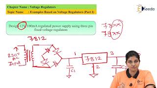
● Design Example:
○ Objective: Design a 5V voltage regulator using an Op-Amp and pass transistor.
○ Solution: Use a 5V reference voltage and the Op-Amp in the feedback loop to control the pass transistor and maintain a steady 5V output, even if the input voltage fluctuates.
Detailed Explanation
This segment dives into linear voltage regulators. These regulators are designed with a component known as the pass element, alongside a voltage reference and an operational amplifier that forms a feedback loop. The Op-Amp continuously monitors the output voltage, comparing it to a stable reference voltage. When differences arise due to changes in load or input voltage, the Op-Amp adjusts the pass element to ensure the output voltage remains constant. A practical design example is highlighted—developing a 5V regulator where the Op-Amp keeps the output steady even amid varying conditions.
Examples & Analogies
Think of a linear voltage regulator as a quality control inspector at a factory, diligently ensuring that every product (output voltage) maintains the same consistent quality (5V) regardless of the materials coming in (input variations). The inspector adjusts the production process if needed to guarantee that every output matches the required specifications.
Switching Voltage Regulators
Chapter 9 of 13
🔒 Unlock Audio Chapter
Sign up and enroll to access the full audio experience
Chapter Content
● Basic Design:
○ Switching regulators use a different approach, where the input voltage is rapidly switched on and off, and the average output is filtered to provide a stable DC voltage.
○ Types of switching regulators:
■ Buck Converter (step-down)
■ Boost Converter (step-up)
■ Buck-Boost Converter (step-up/down)
● Advantages:
○ Efficiency: Switching regulators are more efficient than linear regulators because they do not dissipate excess energy as heat.
○ Complexity: Switching regulators are more complex due to the need for inductors, capacitors, and high-frequency switching components.
Detailed Explanation
Switching voltage regulators adopt a different method compared to linear regulators. They operate by rapidly turning the input voltage on and off while filtering the average output to yield a stable DC voltage. This method leads to several types, such as Buck converters (which reduce voltage), Boost converters (which increase voltage), and Buck-Boost converters (which can either increase or reduce voltage). These regulators are generally more efficient than linear ones, as they minimize wasted energy, albeit at the tradeoff of increased complexity due to additional components required for operation.
Examples & Analogies
Consider switching voltage regulators as efficient delivery services that handle packages (voltage) strategically. They may split or combine shipments based on needs (Buck and Boost), ensuring fewer delays or wasted space compared to a straightforward line service (linear), which could handle everything more simply but may result in wasted resources—like heat in electrical terms.
Stability and Compensation in Voltage Regulators
Chapter 10 of 13
🔒 Unlock Audio Chapter
Sign up and enroll to access the full audio experience
Chapter Content
● Stability:
○ Stability is crucial for maintaining reliable operation, especially in circuits with varying input voltages or loads.
○ Instability can lead to oscillations, noise, or failure to maintain the correct output voltage.
● Compensation Techniques:
○ Feedforward Compensation: Improves the regulator's response to changes in input voltage or load by directly adjusting the feedback loop based on external conditions.
○ Loop Compensation: Affects the phase and gain of the feedback loop to ensure the regulator operates without oscillation or excessive delay.
○ Capacitor Selection: Proper selection of output and input capacitors is essential for maintaining stability, as these components influence the frequency response of the regulator.
Detailed Explanation
In voltage regulators, ensuring stability is paramount to avoid issues such as unwanted oscillations or noise, which can adversely affect performance. Techniques like feedforward compensation are used to enhance responsiveness to changes in load or input by adapting the feedback mechanism accordingly. Loop compensation is another technique focusing on the feedback system's phase and gain to help prevent oscillations and delays. Additionally, selecting the right capacitors plays a significant role in achieving and maintaining stability in the regulator's performance.
Examples & Analogies
Just as a successful orchestra needs a good conductor to coordinate various instruments, voltage regulators require stability techniques to function effectively. If one instrument plays out of sync (unstable condition), it can alter the entire performance. Employing compensation techniques helps ensure that all components work together harmoniously, similar to how a conductor ensures that all parts of an orchestra play well together.
Lab Work on Voltage Regulators
Chapter 11 of 13
🔒 Unlock Audio Chapter
Sign up and enroll to access the full audio experience
Chapter Content
● Objective: Build a linear voltage regulator using an Op-Amp and pass transistor to maintain a constant 5V output.
● Materials:
1. Op-Amp (e.g., LM741)
2. Pass transistor (e.g., 2N2222)
3. Zener diode for voltage reference
4. Resistors, capacitors
5. Power supply and multimeter
● Procedure:
1. Construct the voltage regulator circuit with the Op-Amp and pass transistor.
2. Apply a variable input voltage and measure the output voltage to ensure it remains stable at 5V.
3. Test the regulator with different load currents and verify its ability to maintain the output voltage.
Detailed Explanation
The lab work on voltage regulators aims to provide real-world experience by constructing a linear regulator circuit. The process involves gathering required materials including an Op-Amp and pass transistor. Students will assemble the circuit to maintain a stable 5V output. The next steps include applying various input voltages and observing the output to ensure consistent performance, along with testing the circuit under varying load conditions to validate its design functionality.
Examples & Analogies
Building this circuit can be seen as preparing a meal using a recipe. Gathering ingredients (materials) is essential before assembling (constructing the circuit) and finally adjusting the cooking temperature (varying input voltage) while taste-testing (measuring output) to ensure that the flavor (output voltage) remains just right.
Practical Applications of Comparators and Voltage Regulators
Chapter 12 of 13
🔒 Unlock Audio Chapter
Sign up and enroll to access the full audio experience
Chapter Content
● Comparators:
○ Level Detection: Detects whether a signal exceeds a specified threshold, used in digital systems and control circuits.
○ Zero Crossing Detection: Used in AC waveform analysis and phase-locked loops (PLLs).
○ Pulse Width Modulation (PWM): Generates variable-width pulses for controlling motors, LEDs, or power converters.
● Voltage Regulators:
○ Power Supply Systems: Used in battery-powered devices, power adapters, and DC-DC converters to provide stable voltage to sensitive circuits.
○ Precision Equipment: Ensures that precision analog circuits, such as sensors and amplifiers, receive a stable voltage.
○ Portable Devices: Regulates the voltage in portable systems, ensuring consistent operation despite battery fluctuations.
Detailed Explanation
This section outlines various practical applications for both comparators and voltage regulators. Comparators serve crucial roles in level detection for digital systems, as well as zero crossing detection for analyzing AC signals. They are also employed in PWM for controlling various electronic devices. On the other hand, voltage regulators are essential for power supply systems, providing stable energy to sensitive electronic devices, precision equipment, and portable devices, ensuring all can operate effectively under varying conditions.
Examples & Analogies
Comparators and voltage regulators are like the tools in a kitchen; each has its unique function that contributes to a meal's success. Comparators act like timers giving precise signals when to start or stop cooking, while voltage regulators manage the kitchen’s energy source, ensuring that ovens, fridges, and lights work properly, no matter how many users (devices) demand power at the same time.
Summary of Key Concepts
Chapter 13 of 13
🔒 Unlock Audio Chapter
Sign up and enroll to access the full audio experience
Chapter Content
● Comparators:
○ Comparators are used to compare two input voltages and output a high or low signal based on the comparison.
○ They are widely used in digital logic circuits, signal detection, and waveform generation.
○ Hysteresis is commonly introduced to prevent unwanted switching due to noise.
● Voltage Regulators:
○ Voltage regulators maintain a constant output voltage, ensuring reliable operation of electronic devices.
○ Linear regulators provide smooth output but are less efficient than switching regulators.
○ Stability and compensation techniques are essential for ensuring proper operation of voltage regulators under varying conditions.
Detailed Explanation
This summary recaps the critical points discussed in the chapter. Comparators are highlighted for their role in comparing voltages and generating binary outputs, integral in digital circuits and signal processing, especially with the added benefit of hysteresis for noise reduction. Voltage regulators, in contrast, are crucial for delivering a steady output voltage to sensitive devices, distinguishing between linear and switching types based on efficiency and output smoothness. Techniques for stability and compensation reinforce their reliability in varying conditions.
Examples & Analogies
You can think of this summary like a study guide after finishing a big course. It neatly wraps up everything students learned (the functions of comparators and voltage regulators) while pointing out significant highlights (like the efficiency differences and the use of hysteresis) that ensure they are prepared for exams (real-world applications).
Key Concepts
-
Comparators: Compare two input voltages to produce a digital output.
-
Voltage Regulators: Maintain a constant output voltage for electronic devices.
-
Hysteresis: Introduced in comparators to prevent erratic switching.
-
Linear Regulators: Use feedback mechanisms for voltage stabilization.
-
Switching Regulators: More efficient and complex, employ rapid switching.
Examples & Applications
A comparator might be used to detect temperature thresholds in a thermostat.
Voltage regulators are found in power supply units to ensure consistent voltage for circuits.
Memory Aids
Interactive tools to help you remember key concepts
Rhymes
In a comparator, when voltage is greater, it outputs high, like an elevator!
Stories
Imagine a light switch in a dark room; the only time it turns on is when someone presses it (voltage exceeds a threshold) and turns off when they stop, representing a comparator's function.
Memory Tools
For hysteresis, remember 'High to stay, Low to play' - indicating the necessity of defined thresholds.
Acronyms
VARS
Voltage
Always Regulated Stable - reminds you of the purpose of voltage regulators.
Flash Cards
Glossary
- Comparator
A circuit that compares two voltages and produces a high (logical 1) or low (logical 0) output based on this comparison.
- Voltage Regulator
A device that maintains a constant output voltage despite variations in input voltage or load conditions.
- Hysteresis
The phenomenon where the output state depends on the input voltage's previous states, used to prevent unwanted switching in comparators.
- Linear Voltage Regulator
A type of voltage regulator that maintains a constant output voltage by utilizing a continuous feedback loop.
- Switching Voltage Regulator
A voltage regulator that uses rapid on-off switching to convert input voltage to a desired stable output voltage efficiently.
Reference links
Supplementary resources to enhance your learning experience.