
Impedance Matching Methods
Interactive Audio Lesson
Listen to a student-teacher conversation explaining the topic in a relatable way.
Using Transformers
🔒 Unlock Audio Lesson
Sign up and enroll to listen to this audio lesson

Today, we'll talk about using transformers for impedance matching in RF circuits. Can anyone tell me how impedance matching benefits our circuit designs?

It helps improve power transfer and reduces signal reflection.
Exactly! Transformers use turns ratios to match impedances. The formula we use is Z_load = (N_secondary/N_primary)² × Z_source. Can anyone explain what each term represents?

Z_load is the load impedance, Z_source is the source impedance, and N's are the number of turns.
Great! And remember, transformers can be highly efficient if designed correctly. What are some applications where we might find them?

In antennas and RF power amplifiers!
Correct! Let's summarize: Transformers are crucial for impedance matching due to their efficiency and application in RF circuits.
L-section Matching Networks
🔒 Unlock Audio Lesson
Sign up and enroll to listen to this audio lesson

Now let’s discuss L-section matching networks. Who can tell me what components are involved in this type?

It consists of an inductor and a capacitor.
Correct! In an L-section, the inductor can be in series or parallel with the load. Why do we use L-section networks?
They are simple and effective, especially for narrow frequency bands.
Right! These networks are particularly suited for RF circuits like antennas. Can you think of any reason why we might choose a simple solution over a complex one?
Simplicity means easier design and lower costs!
Exactly! To wrap up, L-section networks are a straightforward and cost-effective way to achieve impedance matching.
Pi-section Matching Networks
🔒 Unlock Audio Lesson
Sign up and enroll to listen to this audio lesson
Next, let's explore pi-section matching networks. How do they differ from L-section networks?
Pi-section networks use two inductors and one capacitor or vice versa.
Yes! They provide better matching over a broader frequency range. Why is that helpful?
Broad matching is important for applications needing precise tuning over various frequencies!
Good point! This flexibility makes them ideal for broadband amplifiers. Let’s conclude this session: Pi-section networks offer versatility and energy efficiency across broader application contexts.
Stub Matching
🔒 Unlock Audio Lesson
Sign up and enroll to listen to this audio lesson
Lastly, let's talk about stub matching. What is a 'stub'?
A short piece of transmission line used to match impedance!
Correct! Stubs can be open-circuited to create capacitance or short-circuited to introduce inductance. Can anyone give me an example of where we might use this?
In RF system designs or for antennas!
Right! Stub matching is a simple and inexpensive solution. Let's recap today's lesson: Stubs are versatile tools in RF systems, providing broad matching capabilities.
Introduction & Overview
Read summaries of the section's main ideas at different levels of detail.
Quick Overview
Standard
The impedance matching methods include transformers, L-section matching networks, pi-section matching networks, and stub matching. Each method has its own advantages and applications, making them vital in enhancing circuit performance in RF and HF applications.
Detailed
Impedance Matching Methods
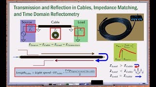
In RF (Radio Frequency) and HF (High Frequency) circuits, impedance matching is essential to ensure that power is efficiently transferred and signal reflections are minimized. This section introduces several key impedance matching methods:
2.3.1 Using Transformers
Transformers are widely used in RF and HF circuits for impedance matching. The impedance transformation is determined by the turns ratio of the transformer. The relationship is given by the equation:
\[ Z_{load} = \left( \frac{N_{secondary}}{N_{primary}} \right)^2 \times Z_{source} \]
Where:
- Zload is the impedance of the load,
- Zsource is the impedance of the source,
- Nsecondary and Nprimary are the number of turns in the respective windings.
Advantages include high efficiency, and they are used in applications such as antennas and RF power amplifiers.
2.3.2 L-section Matching Networks
An L-section matching network consists of one inductor and one capacitor. They can be connected in series with the transmission line or in parallel with the load. This method is straightforward and effective for narrow bandwidths.
Advantages include simplicity and cost-effectiveness, with applications in RF circuits, particularly antennas.
2.3.3 Pi-section Matching Networks
Pi-section networks involve two inductors and one capacitor or vice versa, providing higher flexibility and broader frequency matching compared to L-section networks. The component values are adjusted to ensure effective impedance matching across a wide frequency band, making them suitable for various applications, including broadband amplifiers.
2.3.4 Stub Matching
Stub matching employs a short piece of transmission line connected in parallel or series to introduce capacitive or inductive reactance. For instance, open-circuited and short-circuited stubs introduce different types of reactance, making this method simple and inexpensive, suitable for RF systems and transmission lines.
Each impedance matching method has its specific applications and benefits, ensuring that circuits can function effectively in varying operational contexts.
Youtube Videos
Audio Book
Dive deep into the subject with an immersive audiobook experience.
Using Transformers
Chapter 1 of 4
🔒 Unlock Audio Chapter
Sign up and enroll to access the full audio experience
Chapter Content
Transformers are commonly used in RF and HF circuits to match impedances between components with different impedance values. The transformer’s turns ratio determines the impedance transformation.
Impedance Matching with Transformers:
The impedance ratio is related to the square of the turns ratio nn:
Zload=(NsecondaryNprimary)2×ZsourceZ_{load} = \left(\frac{N_{secondary}}{N_{primary}}\right)^2 \times Z_{source}
Where:
○ ZloadZ_{load} is the impedance of the load.
○ ZsourceZ_{source} is the impedance of the source.
○ NsecondaryN_{secondary} and NprimaryN_{primary} are the number of turns in the secondary and primary windings of the transformer, respectively.
Advantages:
○ High efficiency in transforming impedances.
○ No losses during the transformation if the transformer is designed correctly.
Applications:
○ Used in antennas, transmission lines, and RF power amplifiers.
Detailed Explanation
Transformers are electrical devices that can efficiently change the voltage and current levels in a circuit, which helps in matching the impedance of various circuit components. The effectiveness of a transformer in impedance matching is dictated by its turns ratio; this ratio correlates to how much the impedance is transformed. The formula shown tells us how the load impedance (Zload) can be calculated based on the source impedance (Zsource) and the ratio of the number of turns in the transformer coils. If designed correctly, transformers function with little to no energy loss, making them highly efficient for many RF applications, such as amplifiers and antennas.
Examples & Analogies
Imagine a ramp used in a park to facilitate movement between two different heights. The ramp makes it easy to move from one level to another without a big step that might cause someone to trip. Similarly, a transformer acts as a ramp in an electrical circuit, allowing energy to flow between components with differing impedance without loss, ensuring smooth transmission of electrical signals.
L-section Matching Networks
Chapter 2 of 4
🔒 Unlock Audio Chapter
Sign up and enroll to access the full audio experience
Chapter Content
An L-section matching network consists of one inductor and one capacitor arranged in an L-shape. It is a simple and effective way to match impedance between a source and load. The components can be configured either in series or parallel.
Series L-section:
The inductor is in series with the transmission line, and the capacitor is placed in parallel with the load.
Parallel L-section:
The inductor is in parallel with the transmission line, and the capacitor is placed in series with the load.
Impedance Transformation:
The values of the inductor and capacitor are selected based on the source and load impedances to achieve maximum power transfer.
Advantages:
○ Simple and cost-effective solution.
○ Works well for narrow frequency bands.
Applications:
Often used in narrowband RF circuits like antennas and filter networks.
Detailed Explanation
An L-section matching network is a basic impedance matching circuit that uses two passive components: an inductor and a capacitor. Depending on how you connect these components, they can achieve impedance matching for different situations. In a 'series L-section', the inductor is placed in line with the input, while the capacitor connects to the load, whereas in the 'parallel L-section', the arrangement is reversed. Designers select the values of the inductor and capacitor based on the specific impedances of the source and load they want to match, making it a straightforward and cost-effective method especially useful in applications that operate at narrow frequency bands, such as some antennas.
Examples & Analogies
Think of an L-section matching network like a puzzle. In a simple puzzle, you would have two pieces that need to fit together perfectly without gaps. The inductor and capacitor are like those puzzle pieces; when they are selected and connected correctly, they fit seamlessly to ensure an uninterrupted flow of energy, just like how the completed puzzle provides a clear, cohesive image.
Pi-section Matching Networks
Chapter 3 of 4
🔒 Unlock Audio Chapter
Sign up and enroll to access the full audio experience
Chapter Content
A pi-section network is similar to the L-section, but it involves two inductors and one capacitor or two capacitors and one inductor, forming a "pi" shape. This type of matching network is more flexible and is used when a broader frequency range is needed.
Design:
The components are arranged in a series and parallel combination, and the component values are calculated to match the impedance over a wide frequency band.
Advantages:
○ Provides better matching over a broader frequency range compared to L-section networks.
○ More versatile in applications requiring precise impedance matching.
Applications:
Common in broadband impedance matching, such as for wideband amplifiers or antennas.
Detailed Explanation
The pi-section matching network enhances flexibility for impedance matching by incorporating multiple components—either two inductors and one capacitor or two capacitors and one inductor. The ideal arrangement in a pi-network is that it connects inductors and capacitors both in series and parallel, enabling engineers to fine-tune the circuit for greater bandwidth. This adaptability makes it extremely valuable in applications needing wide frequency support, such as broadband amplifiers that must handle signals over various frequencies with minimal loss.
Examples & Analogies
Imagine a multi-lane highway designed to suit different types of vehicles, where cars, trucks, and motorcycles can all move efficiently without slowing each other down. Just as the highway accommodates various vehicles to ensure smooth traffic flow, the pi-section matching network accommodates different frequencies, allowing various signals to pass through without interference or loss in clarity.
Stub Matching
Chapter 4 of 4
🔒 Unlock Audio Chapter
Sign up and enroll to access the full audio experience
Chapter Content
Stub matching is a technique used to match the impedance of a transmission line to a load using a short piece of transmission line, called a stub, which is connected in parallel or series with the main transmission line.
Types of Stubs:
○ Open-circuited stub: A section of transmission line terminated in an open circuit, used to introduce a capacitive reactance.
○ Short-circuited stub: A section of transmission line terminated in a short circuit, used to introduce an inductive reactance.
Advantages:
○ Simple and inexpensive to implement.
○ Provides a broad matching range for a given frequency.
Applications:
Stub matching is commonly used in RF systems, antenna designs, and transmission lines.
Detailed Explanation
Stub matching is an effective technique involving short lengths of transmission line, termed 'stubs', to achieve desired impedance matching. These stubs can either be left open (creating a capacitive effect) or shorted (creating an inductive effect). This flexibility and ease of implementation make stub matching an economical choice for many systems, particularly where the frequencies are fixed, as they enable greater control over impedance without needing extensive circuit modifications.
Examples & Analogies
Consider the way a baseball player adjusts their bat position to hit the ball more effectively. By pulling the bat back a little (like using an open-circuited stub), they can change the angle of impact to make the hit more effective. Similarly, the stub in a transmission line allows for slight adjustments to ensure that electrical signals match perfectly, optimizing performance.
Key Concepts
-
Impedance Matching: The process of aligning impedances in a circuit to maximize power transfer.
-
Transformers: Devices used for transforming impedance values between circuits.
-
L-section: A matching network using one inductor and one capacitor.
-
Pi-section: A matching network involving two inductors and one capacitor, versatile for broadband applications.
-
Stub Matching: A technique utilizing short lengths of transmission line for impedance matching.
Examples & Applications
Transformers are used in many RF applications like antenna systems to ensure efficient power transfer.
An L-section matching network might be implemented in a mobile phone's antenna to enhance performance.
A pi-section matching network is often found in broadband amplifiers, providing essential impedance matching across a range of frequencies.
Stub matching is commonly used in older radio systems where space and simplicity are priorities.
Memory Aids
Interactive tools to help you remember key concepts
Rhymes
Transformers spin with turns quite grand, matching impedances across the land.
Stories
Imagine a group of friends, each a different height. To reach the tallest tree, they adjust their heights using step stools (transformers), pairs of platforms (L-section), and complex disguises (Pi-section), or they just stretch out their limbs (stub matching) to reach together.
Memory Tools
To remember matching types: T-L-P-S - Transformers, L-section, Pi-section, and Stubs.
Acronyms
For broad matching, think of 'BAM' - Best with Amp Configuration (Pi-section)!
Flash Cards
Glossary
- Impedance Matching
The process of making the impedance of one component equal to that of another to maximize power transfer and minimize signal reflection.
- Transformers
Electrical devices that transfer electrical energy between two or more circuits through electromagnetic induction.
- Turns Ratio
The ratio of the number of turns in the primary coil to the number of turns in the secondary coil of a transformer.
- Lsection Matching Network
A basic impedance matching network using one inductor and one capacitor arranged in an L shape.
- Pisection Matching Network
An impedance matching network consisting of two inductors and one capacitor or vice versa, arranged in a shape resembling the Greek letter 'Pi'.
- Stub Matching
An impedance matching technique using a short piece of transmission line, called a stub, to match the impedance of a load.
Reference links
Supplementary resources to enhance your learning experience.