
Introduction to Impedance Matching
Interactive Audio Lesson
Listen to a student-teacher conversation explaining the topic in a relatable way.
Understanding Impedance
🔒 Unlock Audio Lesson
Sign up and enroll to listen to this audio lesson

Today, we're going to talk about impedance. Can anyone tell me what impedance is?

I think it's something that opposes current flow in circuits.
Exactly! Impedance is the opposition to current flow and can include resistance, inductance, and capacitance. Remember the acronym 'RIC' - Resistance, Inductance, Capacitance.

Why is impedance matching so important in RF circuits?
Great question! In RF circuits, mismatches can lead to signal loss and reflections. Our goal is to minimize these to ensure efficient energy transfer.

So, if mismatched impedances are causing reflection, how does that actually affect the system?
Good point! Reflections can distort signals and cause standing waves, which can interfere with overall system performance. This is why impedance matching is critical.

Can you recap the key points we discussed?
Sure! Impedance is the opposition to current, comprising resistance, inductance, and capacitance. Matching impedances minimizes signal loss and reflections, which is crucial for the efficient operation of RF circuits.
Maximum Power Transfer Theorem
🔒 Unlock Audio Lesson
Sign up and enroll to listen to this audio lesson

Now, let’s delve into the Maximum Power Transfer Theorem. Who can explain what it states?
I think it says that maximum power is transferred when the load impedance equals the source impedance.
That's correct! For reactive loads, we actually need to match the load impedance to the complex conjugate of the source impedance. Remember: 'Match the conjugate!'
Why is this theorem particularly important?
It’s critical in applications like antennas and RF systems where efficient power transfer matters. If we don’t match, we'll experience more signal loss and less efficiency.
So, how does impedance mismatch actually affect the system performance?
Excellent question! Mismatch leads to reflections, which can cause standing waves in transmission lines. It ultimately reduces the efficiency of the circuit.
To summarize, we need to match impedances to maximize power transfer and minimize reflections, right?
Exactly! That’s the essence of the Maximum Power Transfer Theorem.
Consequences of Impedance Mismatch
🔒 Unlock Audio Lesson
Sign up and enroll to listen to this audio lesson
Let’s talk about what happens when impedances are mismatched. What do you think the consequences could be?
Maybe we’ll experience signal loss?
Correct! Signal loss is a major issue. Additionally, there’s distortion and reflections. Who can explain what the reflection coefficient is?
Isn’t it the ratio of reflected signals to incident signals?
Yes, well done! The reflection coefficient tells us how much signal is lost due to mismatch. An ideal reflection coefficient is 0, meaning perfect matching. Remember: 'Zero is perfect!'
What’s SWR again?
SWR, or Standing Wave Ratio, measures the severity of mismatch. Ideally, it should also be 1:1. Summarizing, mismatches lead to signal loss, distortion, and increase SWR.
Introduction & Overview
Read summaries of the section's main ideas at different levels of detail.
Quick Overview
Standard
This section introduces the fundamental concept of impedance matching, emphasizing its importance in RF and HF circuits for optimizing power transfer and reducing signal reflections. Key principles include the Maximum Power Transfer Theorem and the consequences of impedance mismatch, which causes signal loss and distortion.
Detailed
Introduction to Impedance Matching
Impedance matching is a foundational aspect of RF (Radio Frequency) and HF (High Frequency) circuit design aimed at ensuring efficient power transfer and minimizing signal reflections. In alternating current (AC) circuits, impedance represents the opposition to current flow, encompassing resistance, inductance, and capacitance.
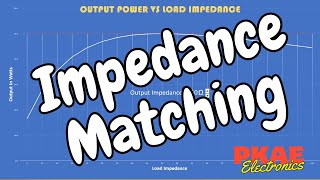
In RF systems, impedance mismatches can lead to significant issues such as signal loss, distortion, and interference due to reflections at the junctions of various circuit components. Impedance matching rectifies this by aligning the impedance values throughout the circuit stages, thus maximizing power transfer and minimizing reflections. Critical principles discussed include the Maximum Power Transfer Theorem, which stipulates that optimal power transfer occurs when the load impedance equals the complex conjugate of the source impedance. Understanding and applying these concepts is essential for professionals working with communication systems, antennas, and RF applications.
Youtube Videos
Audio Book
Dive deep into the subject with an immersive audiobook experience.
Concept of Impedance Matching
Chapter 1 of 3
🔒 Unlock Audio Chapter
Sign up and enroll to access the full audio experience
Chapter Content
Impedance matching is a crucial concept in RF (Radio Frequency) and HF (High Frequency) circuits to ensure efficient power transfer and to minimize signal reflection. Impedance is the opposition to the flow of current in an alternating current (AC) circuit, which includes resistance, inductance, and capacitance.
Detailed Explanation
Impedance matching refers to the adjustment of circuit components to ensure that their impedances are compatible with each other. In RF and HF circuits, it is especially important because it maximizes energy transfer from the source to the load while minimizing any loss due to signal reflection. Impedance is a measure of how much a circuit resists the flow of alternating current, and it is made up of three important factors: resistance (the opposition to current), inductance (the reaction to changes in current), and capacitance (the ability to store electric charge).
Examples & Analogies
Think of impedance matching like making sure the fitting of a hose to a water faucet is just right. If the hose is too big or too small (an impedance mismatch), water might not flow efficiently, leading to leaks or backflow. Similarly, in circuits, if the impedances are mismatched, part of the signal may bounce back instead of flowing smoothly to where it is needed.
Consequences of Impedance Mismatch
Chapter 2 of 3
🔒 Unlock Audio Chapter
Sign up and enroll to access the full audio experience
Chapter Content
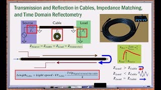
In RF circuits, impedance mismatches can cause signal loss, distortion, and reflection at the interface between different components. These reflections occur when the impedance of the source, transmission line, and load are not equal, leading to inefficient energy transfer and interference.
Detailed Explanation
When impedance mismatches happen, the signals cannot flow as intended. This can result in several problems: the most significant are signal loss, where part of the energy does not reach its destination, distortion, which alters the signal's shape or clarity, and reflection, where part of the signal bounces back toward the source. These issues can create inefficiencies in the circuit and degrade the overall performance of electronic devices.
Examples & Analogies
Imagine a highway where some lanes suddenly become narrower. Cars entering these narrow lanes may not move as smoothly, resulting in bumper-to-bumper traffic (signal distortion) and some cars having to turn back (signal reflection). Properly designed lanes (impedance matching) keep traffic flowing efficiently.
Goals of Impedance Matching
Chapter 3 of 3
🔒 Unlock Audio Chapter
Sign up and enroll to access the full audio experience
Chapter Content
Impedance matching aims to align the impedance values across all stages of a circuit to maximize the power transfer and minimize reflections.
Detailed Explanation
The primary goal of impedance matching is to ensure that the impedances of various components—such as the source, transmission lines, and load—are aligned correctly. When this alignment occurs, it allows for the maximum transfer of signal power from one component to another and minimizes reflections that can lead to losses and inefficiencies. This goal is fundamental in designing circuits for communication and broadcasting technologies, where reliable signal transmission is crucial.
Examples & Analogies
Think of a relay race where runners must smoothly hand off a baton to each other. If the timing or placement is off (impedance mismatch), the baton may drop (signal reflection), and the race slows down (signal loss). Aligning the runners' timing to ensure a smooth handoff (impedance matching) allows the team to run efficiently.
Key Concepts
-
Impedance Matching: Aligning the impedance of source, transmission line, and load for efficient power transfer.
-
Maximum Power Transfer Theorem: States optimal power transfer occurs when load matches source impedance or its complex conjugate.
-
Consequences of Mismatch: Includes signal loss, distortion, and increased SWR.
Examples & Applications
Using a transformer to match impedances in an antenna system to ensure efficient power transfer.
An L-section matching network to match the impedance of an RF amplifier to its load.
Memory Aids
Interactive tools to help you remember key concepts
Rhymes
When circuits do their dance, / Impedance must take a stance, / Match them right, power prance, / Mismatches lead to a chance for loss!
Stories
Imagine a boat trying to dock at a harbor. If the dock (load) and the boat (source) are perfectly aligned (matched impedance), the docking is smooth. If they misalign, it causes chaos; that's like mismatched impedance causing signal distortion.
Memory Tools
Remember 'RIC' for impedance: Resistance, Inductance, Capacitance.
Acronyms
SWR - 'Standing Wave Ratio' indicates how well we match
SWR = (Max Voltage)/(Min Voltage).
Flash Cards
Glossary
- Impedance
The opposition to current flow in an AC circuit, comprised of resistance, inductance, and capacitance.
- Maximum Power Transfer Theorem
The principle stating that maximum power is transferred when load impedance equals the complex conjugate of the source impedance.
- Reflection Coefficient
A measure of how much of the signal is reflected due to impedance mismatch.
- Standing Wave Ratio (SWR)
A ratio measuring the effectiveness of impedance matching; ideally 1:1.
Reference links
Supplementary resources to enhance your learning experience.